
Process for producing lithium batteries having an ultra-high energy density

a lithium battery, ultra-high energy density technology, applied in the direction of non-aqueous electrolyte cells, sustainable manufacturing/processing, cell components, etc., to achieve the effects of high active material mass loading, low overhead weight and volume, and high volumetric capacity

Active Publication Date: 2017-04-06
GLOBAL GRAPHENE GRP INC
View PDF4 Cites 86 Cited by
  • Summary
  • Abstract
  • Description
  • Claims
  • Application Information

AI Technical Summary

Benefits of technology

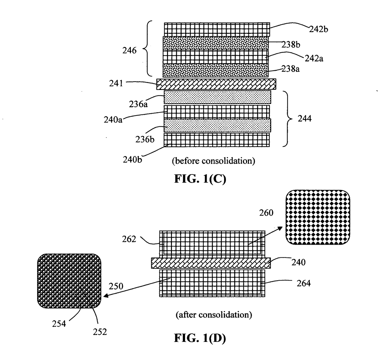
The present invention provides a process for producing a lithium battery with high active material mass loading, low-weight and volume, high volumetric capacity, and unprecedented high volumetric energy density and power density. The process involves creating a wet anode layer containing an anode active material, optional conductive additive and a liquid electrolyte containing a high concentration of lithium salt, which allows for easy handling without dripping. The wet cathode layers have similar properties for easy handling and consolidation. The resulting battery has exceptional performance and is suitable for both primary and secondary batteries.

Problems solved by technology

This and several other batteries from different manufacturers were abandoned due to a series of safety problems caused by sharply uneven Li growth (formation of Li dendrites) as the metal was re-plated during each subsequent recharge cycle.
As the number of cycles increases, these dendritic or tree-like Li structures could eventually traverse the separator to reach the cathode, causing internal short-circuiting.
However, the use of graphite-based anodes in Li-ion batteries has several significant drawbacks: low specific capacity (theoretical capacity of 372 mAh / g as opposed to 3,860 mAh / g for Li metal), long Li intercalation time (e.g. low solid-state diffusion coefficients of Li in and out of graphite and inorganic oxide particles) requiring long recharge times (e.g. 7 hours for electric vehicle batteries), inability to deliver high pulse power (power density <<1 kW / kg), and necessity to use pre-lithiated cathodes (e.g. lithium cobalt oxide), thereby limiting the choice of available cathode materials.
Further, these commonly used cathodes have a relatively low specific capacity (typically <200 mAh / g).
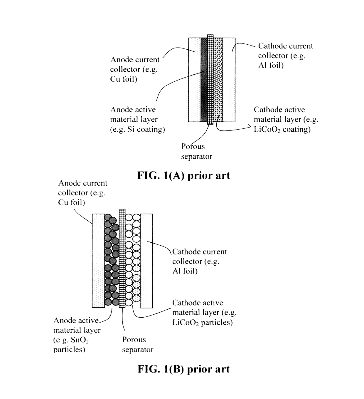
However, the dramatic volume changes (up to 380%) of Si during lithium ion alloying and de-alloying (cell charge and discharge) often led to severe and rapid battery performance deterioration.
The performance fade is mainly due to the volume change-induced pulverization of Si and the inability of the binder / conductive additive to maintain the electrical contact between the pulverized Si particles and the current collector.
In addition, the intrinsic low electric conductivity of silicon is another challenge that needs to be addressed.
Although several high-capacity anode active materials have been found (e.g., Si), there has been no corresponding high-capacity cathode material available.
Current cathode active materials commonly used in Li-ion batteries have the following serious drawbacks:(1) The practical capacity achievable with current cathode materials (e.g. lithium iron phosphate and lithium transition metal oxides) has been limited to the range of 150-250 mAh / g and, in most cases, less than 200 mAh / g.(2) The insertion and extraction of lithium in and out of these commonly used cathodes rely upon extremely slow solid-state diffusion of Li in solid particles having very low diffusion coefficients (typically 10−8 to 10−14 cm2 / s), leading to a very low power density (another long-standing problem of today's lithium-ion batteries).(3) The current cathode materials are electrically and thermally insulating, not capable of effectively and efficiently transporting electrons and heat.
The low thermal conductivity also implies a higher tendency to undergo thermal runaway, a major safety issue in lithium battery industry.
There are serious design and manufacturing issues that the lithium-ion battery industry does not seem to be aware of, or has largely ignored.
For instance, despite the high gravimetric capacities at the electrode level (based on the anode or cathode active material weight alone) as frequently claimed in open literature and patent documents, these electrodes unfortunately fail to provide batteries with high capacities at the battery cell or pack level (based on the total battery cell weight or pack weight).
This is due to the notion that, in these reports, the actual active material mass loadings of the electrodes are too low.
The low active material mass loading is primarily due to the inability to obtain thicker electrodes (thicker than 100-200 μm) using the conventional slurry coating procedure.
Contrarily, thicker samples tend to become extremely brittle or of poor structural integrity and would also require the use of large amounts of binder resin.
The low areal densities and low volume densities (related to thin electrodes and poor packing density) result in a relatively low volumetric capacity and low volumetric energy density of the battery cells.

Method used


Image

  • Process for producing lithium batteries having an ultra-high energy density
  • Process for producing lithium batteries having an ultra-high energy density
  • Process for producing lithium batteries having an ultra-high energy density

Examples


example 1

ive Examples of Electronically Conductive Porous Layers as a Porous Building Block for Current Collectors

[0126]Various types of metal foams and fine metal webs / screens are commercially available for use as an anode or cathode foam structure (current collector); e.g. Ni foam, Cu foam, Al foam, Ti foam, Ni mesh / web, stainless steel fiber mesh, etc. Metal-coated polymer foams and carbon foams are also used as current collectors. The most desirable thickness ranges for these conductive porous layers are 50-1000 μm, preferably 50-500 μm, more preferably 50-200 μm.

example 2

nd CVD Graphene Foam-Based Porous Layers Supported on Ni Foam Templates

[0127]The procedure for producing CVD graphene foam was adapted from that disclosed in open literature: Chen, Z. et al. “Three-dimensional flexible and conductive interconnected graphene networks grown by chemical vapor deposition,” Nature Materials, 10, 424-428 (2011). Nickel foam, a porous structure with an interconnected 3D scaffold of nickel was chosen as a template for the growth of graphene foam. Briefly, carbon was introduced into a nickel foam by decomposing CH4 at 1,000° C. under ambient pressure, and graphene films were then deposited on the surface of the nickel foam. Due to the difference in the thermal expansion coefficients between nickel and graphene, ripples and wrinkles were formed on the graphene films. Four types of foams made in this example were used as a current collector in the presently invented lithium batteries: Ni foam, CVD graphene-coated Ni form, CVD graphene foam (Ni being etched awa...

example 3

Foam-Based Conductive Porous Layers from Pitch-Based Carbon Foams

[0130]Pitch powder, granules, or pellets are placed in a aluminum mold with the desired final shape of the foam. Mitsubishi ARA-24 meso-phase pitch was utilized. The sample is evacuated to less than 1 torr and then heated to a temperature approximately 300° C. At this point, the vacuum was released to a nitrogen blanket and then a pressure of up to 1,000 psi was applied. The temperature of the system was then raised to 800° C. This was performed at a rate of 2 degree C. / min. The temperature was held for at least 15 minutes to achieve a soak and then the furnace power was turned off and cooled to room temperature at a rate of approximately 1.5 degree C. / min with release of pressure at a rate of approximately 2 psi / min. Final foam temperatures were 630° C. and 800° C. During the cooling cycle, pressure is released gradually to atmospheric conditions. The foam was then heat treated to 1050° C. (carbonized) under a nitroge...


PUM

PropertyMeasurementUnit
thicknessaaaaaaaaaa
thicknessaaaaaaaaaa
thicknessaaaaaaaaaa

Abstract

A process for producing a lithium battery, comprising: (A) Preparing a plurality of conductive porous layers, wet anode layers, and wet cathode layers; (B) Stacking a desired number of porous layers and wet anode layers in an alternating manner to form an anode electrode having a thickness no less than 100 μm; (C) Placing a porous separator layer in contact with the anode electrode; (D) Stacking a desired number of porous layers wet cathode layers in an alternating manner to form a cathode electrode in contact with the porous separator, wherein the cathode electrode has a thickness no less than 100 μm; and (F) Assembling and sealing the anode electrode, separator, and cathode electrode in a housing to produce the lithium battery. The consolidated anode or cathode layer is preferably thicker than 300 more preferably thicker than 400 μm, and further more preferably greater than 500 μm.

Description

FIELD OF THE INVENTION[0001]The present invention relates generally to the field of lithium batteries, including primary and secondary (rechargeable) lithium metal batteries and lithium-ion batteries.BACKGROUND OF THE INVENTION[0002]Historically, today's most favorite rechargeable energy storage devices—lithium-ion batteries—actually evolved from rechargeable “lithium metal batteries” using lithium (Li) metal or Li alloy as the anode and a Li intercalation compound as the cathode. Li metal is an ideal anode material due to its light weight (the lightest metal), high electronegativity (−3.04 V vs. the standard hydrogen electrode), and high theoretical capacity (3,860 mAh / g). Based on these outstanding properties, lithium metal batteries were proposed 40 years ago as an ideal system for high energy-density applications. During the mid-1980s, several prototypes of rechargeable Li metal batteries were developed. A notable example was a battery composed of a Li metal anode and a molybden...

Claims


Application Information

Patent Timeline
Patent Type & Authority Applications(United States)
IPC IPC(8): H01M10/058H01M4/80H01M4/66H01M4/133H01M4/583H01M4/48H01M4/136H01M4/58H01M4/131H01M4/525H01M4/60H01M4/52H01M6/14H01M6/02H01M10/0525
CPCH01M10/058H01M6/02H01M4/808H01M4/663H01M4/133H01M4/583H01M4/483H01M4/136H01M4/5825H01M4/131H01M4/525H01M4/60H01M4/606H01M4/523H01M6/14H01M10/0525H01M4/13H01M4/386H01M4/502H01M4/587H01M10/0585Y02E60/10Y02P70/50H01M2300/0085
Inventor ZHAMU, ARUNAJANG, BOR Z.
Owner GLOBAL GRAPHENE GRP INC
Learn More