Eureka AIR delivers breakthrough ideas for toughest innovation challenges, trusted by R&D personnel around the world.

Membrane and device for treating hemolytic events

a membrane and hemolytic technology, applied in the field of membranes for hemolytic events, can solve the problems of affecting the treatment effect of patients, affecting the treatment effect, and affecting the patient's hemolytic status, so as to achieve the effect of effectively addressing acute and/or chronic hemolytic events, high cut-off membranes, and high permeability

Active Publication Date: 2016-11-17
GAMBRO LUNDIA AB
View PDF2 Cites 2 Cited by
  • Summary
  • Abstract
  • Description
  • Claims
  • Application Information

AI Technical Summary

Benefits of technology

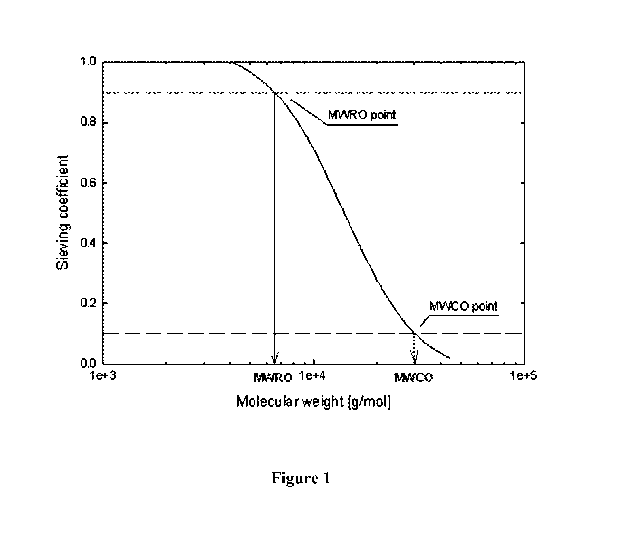
The present invention provides a method of treating hemolysis in a patient by removing hemoglobin from the patient's blood. This is achieved by withdrawing and bypassing the blood from the patient in a continuous flow into contact with one face of an hemodialysis membrane, simultaneously passing dialysate solution in a continuous flow on an opposite face of the hemodialysis membrane to the side of the blood, and returning the blood into the patient. The hemodialysis membrane is characterized in that it comprises at least one hydrophobic polymer and at least one hydrophilic polymer and has a MWRO of between 9 and 20 kD and a MWCO of between 55-320 kD. This membrane has good properties for treating hemolysis and has been found to be effective in removing hemoglobin from the blood.

Problems solved by technology

Cell-free plasma hemoglobin concentrations of >0.1 g / L are generally perceived as undesirable for a patient.
However, in hemolytic anemia, the bone marrow can't make red blood cells fast enough to meet the body's needs, and the patient becomes “anemic” because of the high rates of red blood cell destruction.
Acute symptoms may include chills, rigors, dyspnoea, chest and / or flank pain, sense of dread, confusion, abnormal bleeding and may progress rapidly to shock, which is life-threatening.
This may be a fatal reaction.
In some patients ongoing hemolysis may result in enlarged spleen and / or liver, an enlarged heart and even heart failure.
Gallstones or an enlarged spleen may cause pain in the upper abdomen.
Kidney damage may result as excess hemoglobin crystallizes and obstructs the renal tubules, producing renal shutdown and uremia.
Intravenous administration of a hypotonic solution or plain distilled water will also destroy red blood cells by causing them to fill with fluid until their membranes rupture.
The most common cause is transfusion of ABO / Rh incompatible blood due to clerical errors or patient identification errors such as improper labelling of samples, administering blood to the wrong patient or testing errors.
Another cause of this type of transfusion reaction can be the presence of red cell alloantibodies (non-ABO) in the patient's plasma which have not been previously identified.
Occasionally a patient may have an antibody at levels below the detection capabilities of the antibody screening method or a clerical error occurs in the labelling of patient samples.
A great variety of chemical agents can lead to destruction of erythrocytes if there is exposure to a sufficiently high concentration of the substance.
Physical damage to red blood cells can also occur when red blood cells are damaged during heart-lung surgery or if they are exposed to extreme heat, as in a patient with severe burns.
Extracorporeal blood flow cannot be avoided in extracorporeal blood purification therapies; consequently, CPH levels are often elevated by such treatments (Polaschegg H D. Red blood cell damage from extracorporeal circulation in HD.
At such concentrations, the capacity of the haptoglobin scavenging system is clearly exceeded, and adverse outcomes associated with elevated levels of CPH occurred.
HD-induced release of hemoglobin limits nitric oxide bioavailability and impairs vascular function.
The findings of Polaschegg et al., Lou et al., Mayer et al. and Betrus et al. seem to indicate that currently available dialyzers and membranes for use in hemodialysis cannot contribute to reducing hemoglobin concentrations during either acute hemolytic episodes or chronic settings such as in hemodialysis.

Method used


Image

  • Membrane and device for treating hemolytic events
  • Membrane and device for treating hemolytic events
  • Membrane and device for treating hemolytic events

Examples


example 1

Materials and Methods Used for Simulated Dialysis Treatments with Blood or Plasma

1.1 Dialyzers

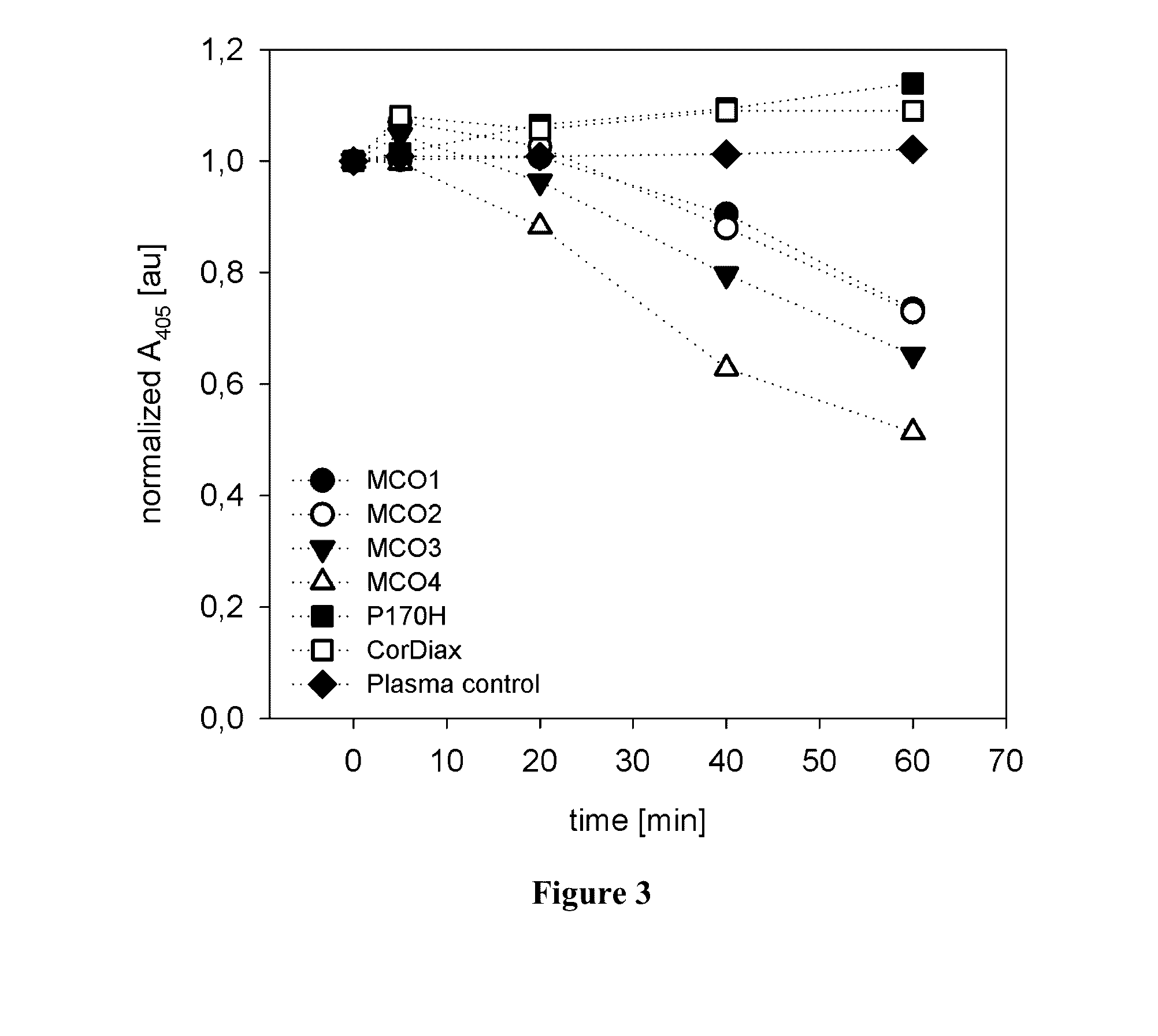
[0075]The dialyzers used in the simulated treatments were the following: septeX 1.1 m2 (Gambro Dialysatoren GmbH, Hechingen, Germany), Polyflux 170H, 1.7 m2 (P170H) (Gambro Dialysatoren GmbH, Hechingen, Germany), four high-flux dialyzers with extended permeability which were prepared in accordance with PCT / EP2015 / 052364 (1.8 m2, herein referred to as MCO1-4; Gambro Dialysatoren GmbH, Hechingen, Germany), and FX CorDiax80 1.8 m2 (Fresenius Medical Care, Bad Homburg, Germany). Within the different types of MCO prototypes the permeability increased from MCO1 to MCO4. MCO 4 comprises a membrane which was prepared according to Example 1.1 of PCT / EP2015 / 052364. MCO 1 through 3 are based on membranes with the same recipe and the same spinning conditions, with the exception of the temperature chosen for spinning head (SH) and spinning shaft (SS), i.e. 56° C. (SH) and 53° C. (SS) for MCO 1, 57° C. (...

example 2

Hemoglobin Clearance of septeX in Blood and Plasma

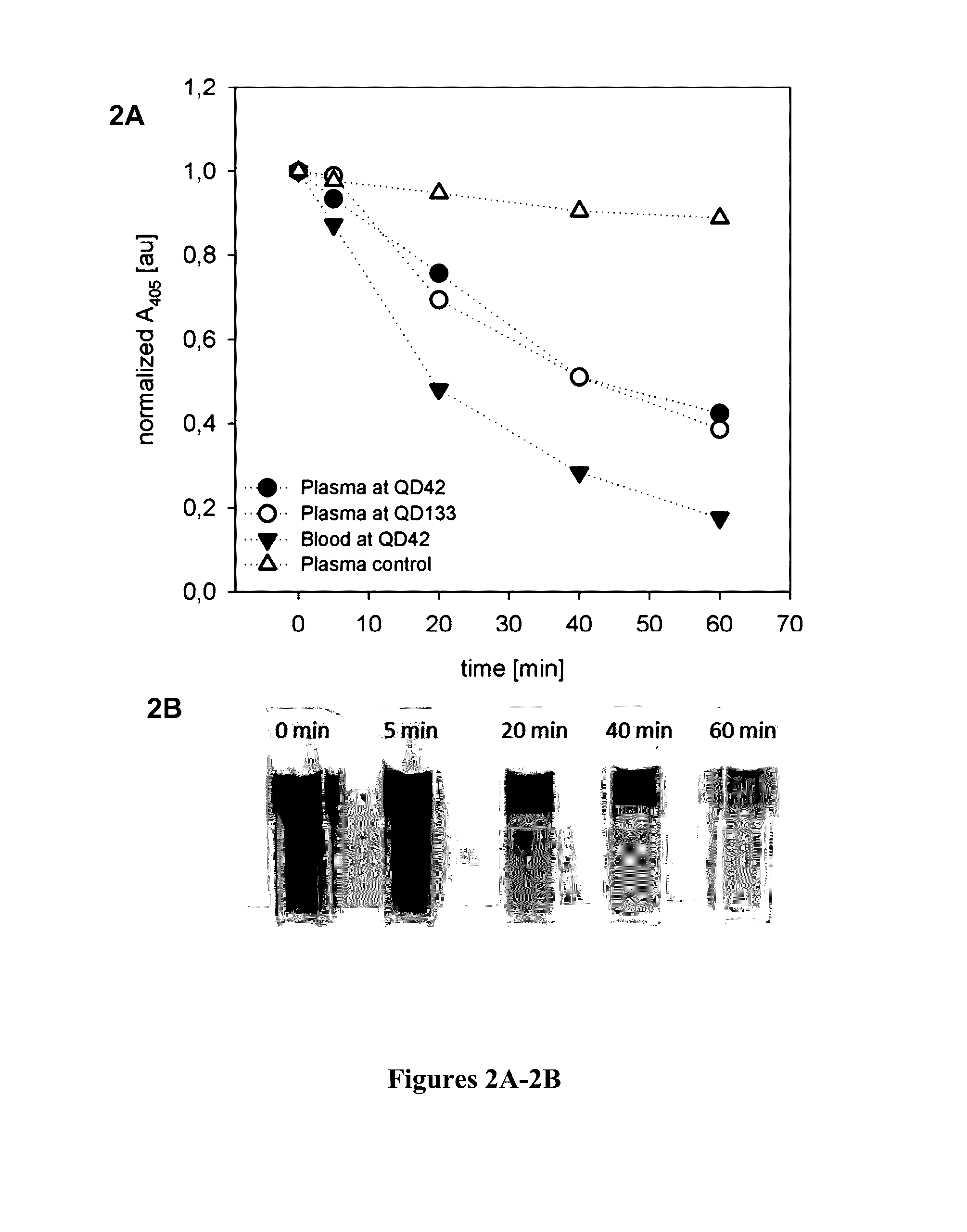
[0086]Simulated dialysis treatments with septeX™ were conducted on a Prismaflex monitor using whole blood or plasma, and the plasma absorbance was measured at 405 nm at defined times. The plasma absorbance at the beginning of the experiment was normalized to a value of 1, and the remaining values for each experiment were related to this starting value. FIGS. 2A-2B show the time course of the plasma absorbance under various test conditions. Photographs of the plasma samples taken from the run using whole blood are shown at the bottom of FIG. 2B. When the simulated treatments were performed in the absence of CPH, the plasma absorbance at 405 nm was decreased by approximately 10% (“plasma control” in FIG. 2A). This decrease in absorbance cannot specifically be related to the decrease in CPH. Therefore, plasma control runs were taken as a baseline for the following CPH clearance calculations based on the variations of the plasma absorban...

example 3

Hemoglobin Clearance of High-Flux Dialyzers in Plasma and Blood

[0088]Simulated dialysis treatments with high-flux dialyzers were conducted on an AK 200 Ultra monitor using plasma and blood. The plasma absorbance at 405 nm was measured at defined times. The plasma absorbance at the beginning of the experiment was normalized to a value of 1, and the remaining values for each experiment were related to this starting value. Time courses of the plasma absorbance for the different tested filters are shown in FIG. 3 (tests using plasma) and FIG. 4 (tests using whole blood). When the simulated treatments were performed in the absence of CPH, the plasma absorbance at 405 nm remained constant (“plasma control” in FIG. 3). Therefore, absorbance changes could be related directly to decreases in CPH. In the case of CorDiax and P170H, there was a slight increase in the absorbance over time; however, for the MCO-type filters, the absorbance at 405 nm steadily decreased. CPH clearances were calcula...


PUM

PropertyMeasurementUnit
concentrationaaaaaaaaaa

Abstract

The present disclosure relates to a hemodialysis membrane for the treatment of hemolytic events, especially acute episodes of hemolysis which lead to elevated levels of plasma free hemoglobin. The present disclosure further relates to methods of removing hemoglobin from the blood of patients undergoing a hemolytic event. The treatment and method encompasses using a hemodialysis membrane which is characterized in that it comprises at least one hydrophobic polymer and at least one hydrophilic polymer and in that it has a MWRO of between 15 and 20 kD and a MWCO of between 170-320 kD, or, in the alternative, has a MWRO of between 9 and 14 kD and a MWCO of between 55 kD and 130 kD.

Description

CROSS-REFERENCE TO RELATED APPLICATIONS[0001]This application claims priority to European Patent Application 15167828.1, filed on May 15, 2015. The disclosure of European Patent Application 15167828.1 is hereby incorporated herein by reference in its entirety.TECHNICAL FIELD[0002]The present disclosure relates to a hemodialysis membrane for the treatment of hemolytic events, especially acute episodes of hemolysis which lead to elevated levels of cell-free plasma hemoglobin. The present disclosure therefore also relates to methods of removing hemoglobin from the blood of patients undergoing a hemolytic event. The treatment and method encompasses using a hemodialysis membrane which is characterized in that it comprises at least one hydrophobic polymer and at least one hydrophilic polymer and in that it has a MWRO of between 15 and 20 kD and a MWCO of between 170-320 kD, or, in the alternative, has a MWRO of between 9 and 14 kD and a MWCO of between 55 kD and 130 kD.DESCRIPTION OF THE ...

Claims


Application Information

Patent Timeline
Patent Type & Authority Applications(United States)
IPC IPC(8): A61M1/34B01D69/08B01D71/40B01D69/02B01D61/24B01D71/68
CPCA61M1/3496A61M1/3424B01D61/243B01D2325/34B01D71/40B01D69/02B01D69/08B01D71/68A61M1/16B01D71/4011B01D2325/20A61M1/1621
Inventor STORR, MARKUSKRAUSE, BERNDHULKO, MICHAELAMON, OLIVER
Owner GAMBRO LUNDIA AB
Why Eureka
Eureka Blog
Learn More