
Inductor and method of manufacturing the same

Inactive Publication Date: 2014-01-02
SAMSUNG ELECTRO MECHANICS CO LTD
View PDF0 Cites 20 Cited by
  • Summary
  • Abstract
  • Description
  • Claims
  • Application Information

AI Technical Summary

Benefits of technology

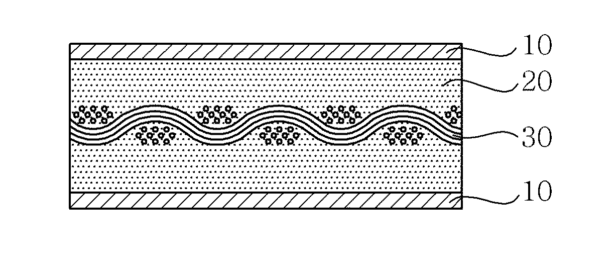
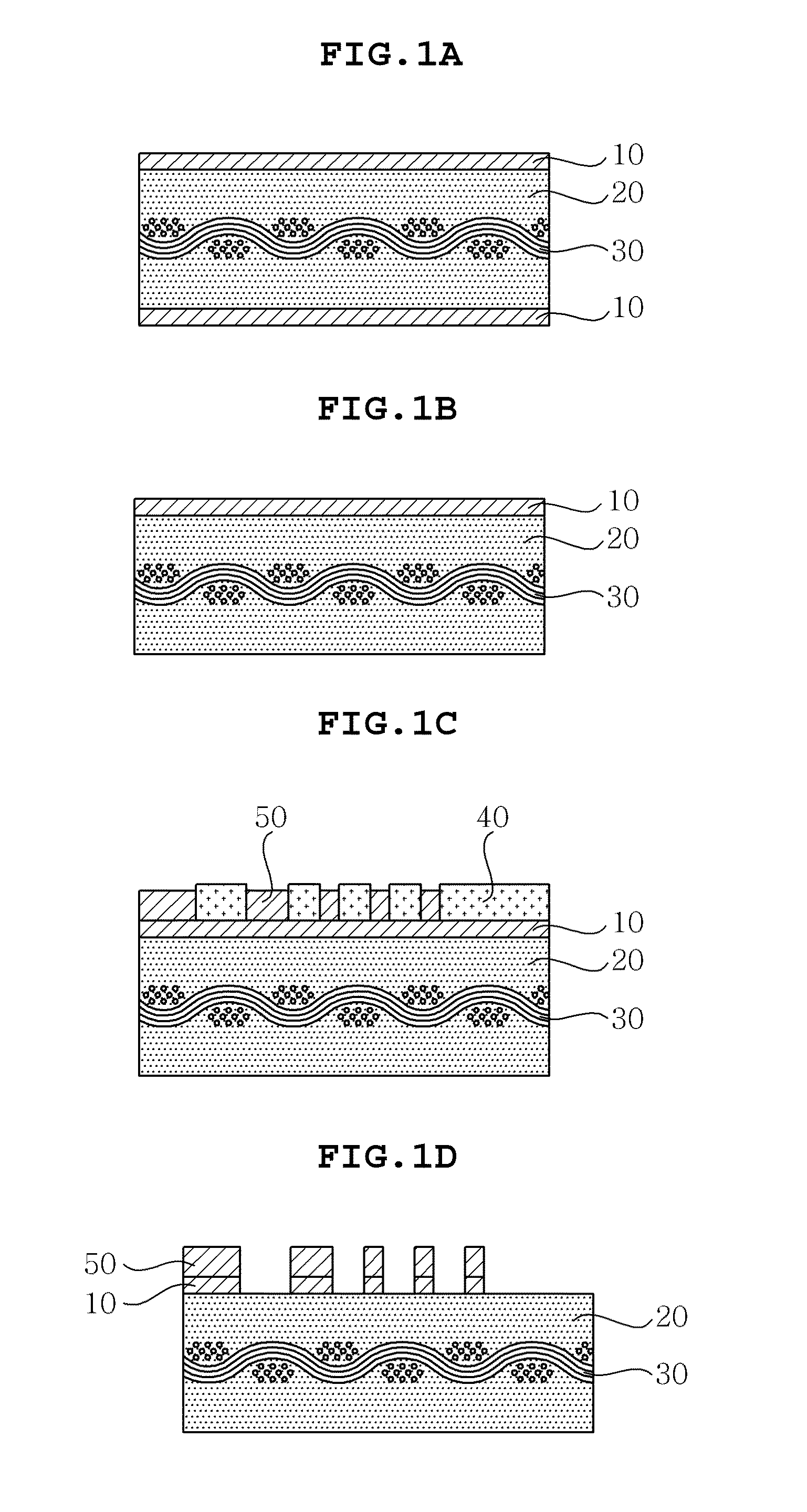
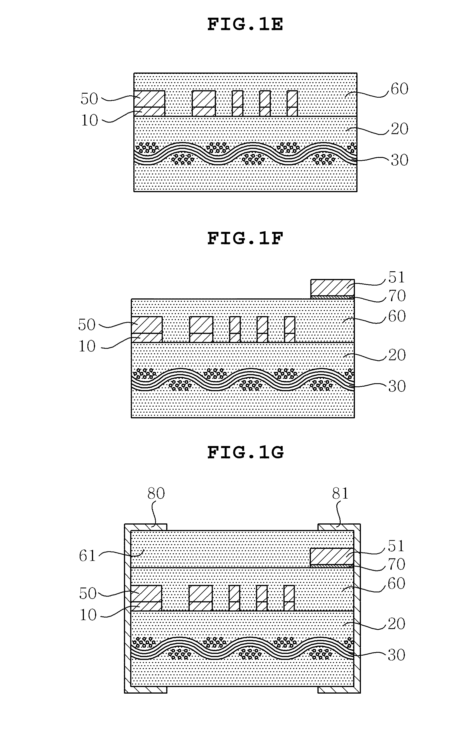
The present invention is about making an inductor with low dielectric loss and better Q-factor. It also describes a method of manufacturing it through an insulating substrate, which allows for smaller patterns and reduces coil deformation without needing a firing process.

Problems solved by technology

In the prior art, a component such as an inductor has been manufactured using a ceramic material due to electrical characteristics such as high dielectric constant, inductance, or the like, and characteristics such as low thermal expansion coefficient, high strength, or the like, but there arise problems that deformation of a coil easily occurs by smearing of an electrode in a printing process, or alignment deviation or a pressed electrode at the time of laminating and pressing, and deformation of a coil shape develops too much due to contractive deformation at the time of firing.
Therefore, accuracy of the inductance in a high frequency region may be reduced, and it may be difficult to reduce a size of the inductor and achieve high-frequency due to low Q characteristics.
However, in the multi-layered form, an overall thickness of a lamination is increased, and excellent Q characteristics are not realized due to contractive deformation or the like in a firing process.

Method used


Image

  • Inductor and method of manufacturing the same
  • Inductor and method of manufacturing the same
  • Inductor and method of manufacturing the same

Examples


preparation example

Preparation of Liquid Crystal Oligomer

[0070]4-aminophenol (2.0 mol), isophthalic acid (2.5 mol), 4-hydroxy benzoic acid (2.0 mol), 6-hydroxy-2-naphthoix acid (1.5 mol), and acetic anhydride (15 mol) were added to a reactor. An inside of the reactor is sufficiently substituted with a nitrogen gas, a temperature in the reactor rose to about 230° C. under a flow of nitrogen gas, and then the inside of the reactor was refluxed for about 4 hours while maintaining the temperature in the reactor at 230° C. Next, 6-hydroxy-2-naphthoic acid (1.0 mol) for distal end capping was additionally added, and acetic acid which was reaction by-products and unreacted acetic anhydride were removed, thereby preparing the liquid crystal oligomer represented by Chemical Formula 1.

example 1

[0071]Silica having an average particle size of 0.2 μm to 1 μm was dispersed in 2-methoxy ethanol, thereby preparing a silica slurry having a concentration of 70 weight %. Next, 15.8 weight % of bisphenol F-type epoxy resin represented by Chemical Formula 2 was added to the prepared silica slurry (the content of silica being 60 weight %), and then the silica slurry was agitated at 300 rpm using an agitator at room temperature to thereby be dissolved, thereby preparing a mixture.

[0072]Next, 0.2 weight % of dicyan diamide and 24 weight % of the liquid crystal oligomer obtained in the preparation example 1, which was dissolved in dimethylacetamide, were added to the mixture, and was agitated at 300 rpm for further 1 hour. Next, 3 g of 2-ethyl-4-methyl imidazole and a leveling agent (BYK-337) were added with 1.5 PHR (Parts per Hundred parts of Resin) of the entire mixture, and then was agitated for 1 hour, thereby preparing an insulating epoxy resin composite.

[0073]In this manner, the p...


PUM


Abstract

Disclosed herein are an inductor and a method of manufacturing the same. More specifically, in the inductor according to the present invention, a coil with a fine pattern may be formed, and an insulating resin composite including liquid crystal oligomer for reducing occurrence of deformation of the coil may be used for an insulating substrate.

Description

CROSS REFERENCE TO RELATED APPLICATION[0001]This application claims the benefit of Korean Patent Application No. 10-2012-0070824, filed on Jun. 29, 2012, entitled “Inductor and Method of Manufacturing The Same”, which is hereby incorporated by reference in its entirety into this application.BACKGROUND OF THE INVENTION[0002]1. Technical Field[0003]The present invention relates to an inductor and a method of manufacturing the same.[0004]2. Description of the Related Art[0005]With the development of miniaturization and complex functionalization of mobile devices, demands for micro-miniaturization of electronic components have increased, and electrical, thermal, and mechanical characteristics of electronic materials may be exerted as important elements. An inductor is one of the important passive devices composed of an electronic circuit together with a resistor and a capacitor, and used as a component that eliminates noise or includes an LC resonator circuit.[0006]In the prior art, a c...

Claims


Application Information

Patent Timeline
IPC IPC(8): H01F41/12H01F27/00
CPCH01F41/125H01F27/00H01F17/0013H01F27/292H01F41/041H01F17/00H01F41/06
Inventor MOON, JIN SEOKWI, SUNG KWONLEE, JEONG KYULEE, KEUN YONGLEE, HYUN JUNYOO, SEONG HYUN
Owner SAMSUNG ELECTRO MECHANICS CO LTD
Learn More