
Methods to Improve the Electrical Conductivity for Moulded Plastic Parts

a technology of plastic parts and electrical conductivity, which is applied in the field of polymer processing, can solve the problems of difficult to obtain good electrical conductivity, difficult to meet the moulding requirements of complex and high-precision micro-parts, and significant differences in electrical conductivity at different locations in moulded parts, so as to improve electrical conductivity and high strain rate and stress.

Inactive Publication Date: 2014-01-02
UNIVERSITY OF BRADFORD +1
View PDF6 Cites 10 Cited by
  • Summary
  • Abstract
  • Description
  • Claims
  • Application Information

AI Technical Summary

Benefits of technology

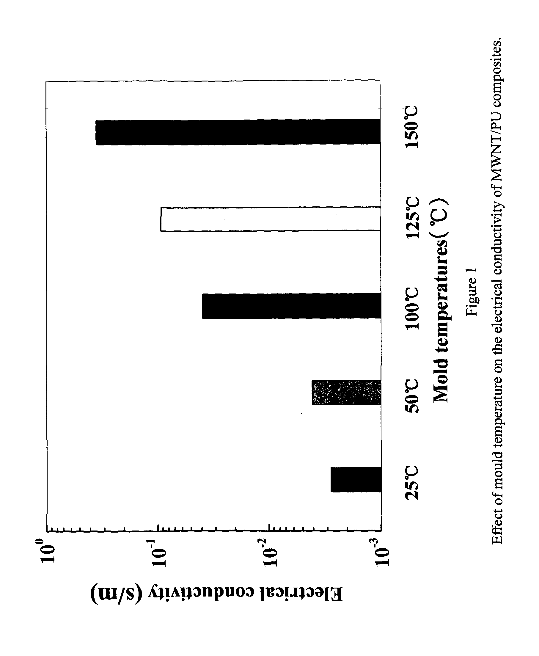
The patent text describes how plastic microparts can be made more conductive through a process called annealing. This involves subjecting the microparts to a post-thermal treatment to enhance their electrical conductivity. The microparts can be made by molding polymer and carbon nanotube composites using methods like micro extrusion, micro injection molding, and hot embossing. The mold used for shaping can be made of plastic or ceramics, with a preferred temperature of TmA higher temperature is better for both micro injection molding and hot embossing. The cooling medium used for micro extrusion can be hot air or water bath with a temperature between room temperature to TmBetter results can be achieved with a higher temperature cooling medium.

Problems solved by technology

In some cases the traditional polymer materials have not been able to meet the moulding requirements of complicated and high precision microparts.
Major challenges encountered in making such a composite are: (a) the uniform dispersion of CNTs in a polymer matrix without agglomerates and entanglements, and (b) CNTs / resin interface adhesion.
For moulded plastic parts of polymer / CNTs nanocomposites, it is difficult to obtain good electrical conductivity.
Due to its high shear effect, the micromoulding process severely breaks down the conductive network and contact of CNTs, although, this process also facilitates the dispersion of CNTs in the polymer melt.
Also, there is significant difference in the electrical conductivity at different locations in the moulded parts caused by the effect of high shear gradient and temperature gradient.

Method used


Image

  • Methods to Improve the Electrical Conductivity for Moulded Plastic Parts
  • Methods to Improve the Electrical Conductivity for Moulded Plastic Parts
  • Methods to Improve the Electrical Conductivity for Moulded Plastic Parts

Examples


example 1

[0032](1) Multi-walled Carbon Nanotube (MWNT)

[0033]MWNT (Product number: C7000) with a diameter of 15 nm, product of Nanocyl, Belgium was used.

[0034](2) Thermoplastic polyurethane elastomer (PU)

[0035]PU (Product number: ESA-480) with shore hardness 80A, product of Shenzhen Pepson Company, China was used.

[0036]Firstly, 30 g MWNT and 270 g dried pelletized PU were firstly well mixed and then blended in a twin-screw extruder (L / D: 36, model: SHJ-25, Nanjing ChengMeng Plastics Machinery Industry Company, Ltd, China) in the range of 185-195° C. and a screw speed of 120 rpm. The extrudate was quenched in a water bath, cut into pellets and then dried in a vacuum oven at 100° C. for 8 h. The MWNT / PU masterbatch with 10 wt % MWNT were prepared.

[0037]Secondly, 200 g of pellets of this master batch and 200 g PU were blended in the twin-screw extruder again under the same processing conditions as the first step. The extrudate was quenched in a water bath, cut into pellets, and dried in a vacuum...

example 2

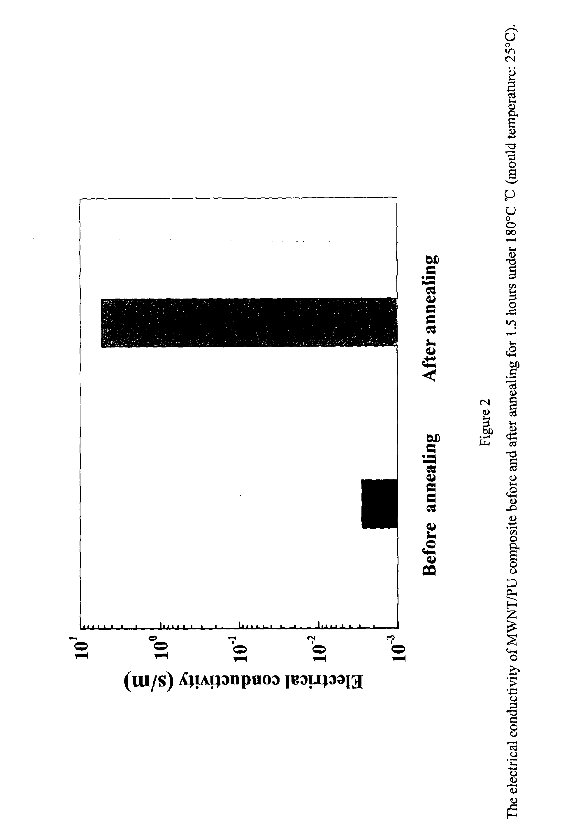
[0041]MWNT / PU composites were prepared as the same process in Example 1. The composites were micro injection moulded through a HAAKE MiniJet machine. The micro injection moulding process was conducted at a cylinder temperature of 210° C., an injection time of 10 s, an injection pressure of 77 MPa, a holding pressure of 20 MPa, a holding time of 10 seconds and a mould temperature of 25° C., The post thermal treatment was as follows: the micro injection moulded plastic parts were subject to thermal annealing treatment for 1.5 hours at 180° C. in an electric resistive heating oven. The electrical conductivity of micromoulded plastic parts is about 5.4 S. m−1. FIG. 2 shows the electrical conductivity of MWNT / PU composites before and after annealing for 1.5 hours under 180° C. The electrical conductivity of the MWNT / PU composite increased from 0.0028 s / m to 5.3597 s / m after annealing for 1.5 hours under 180° C.

example 3

[0042]15 g MWNT, 2 g diphenylamine, tristearin 2 g and 270 g high density polyethylene (HDPE, SH800, China petroleum & chemical corporation) with a melt flow index of 8.0 g / 10 min were firstly mixed and then blended in a twin-screw extruder in the temperature range of 185-195° C. and a screw speed of 120 rpm. The extrudate was quenched in a water bath, cut into pellets and then dried in a vacuum oven at 100° C. for 2 h. Then the pellets were micro injection moulded through a HAAKE MiniJet machine at a cylinder temperature of 210° C., an injection time of 10 s, an injection pressure of 77 MPa, a holding pressure of 20 Mpa, a holding time of 10 seconds and a mould temperatures of 25° C. The post thermal treatment was as follows: the micro injection moulded plastic parts were subject to thermal annealing treatment for 1.5 hours at 180° C. in an electric resistive heating oven. The electrical conductivity of the micro injection moulded MWNT / HDPE sample is ˜30S. m−1.


PUM

PropertyMeasurementUnit
Temperatureaaaaaaaaaa
Diameteraaaaaaaaaa
Diameteraaaaaaaaaa

Abstract

Disclosed herein are the methods to improve the electrical conductivity for micro-moulded plastic parts containing carbon nanotubes. The polymer / carbon nanotubes composites suitable for polymer micromoulding including 80˜99.95 wt % of a polymer pellet or powder, 0-2 wt % of antioxidant, 0-2 wt % of dispersant agent and 0.05-20 wt % of carbon nanotube with a diameter 0.5-200 nm and a length of 200 nm-20 μm are firstly prepared through melt extrusion. The plastic microparts are prepared by micromoulding of the polymer / carbon nanotubes composites including micro extrusion, micro injection and hot embossing at optimized processing conditions and then are subject to a post thermal treatment to enhance the electrical conductivity. The post thermal treatment methods include electric heating, microwave, infrared or plasma heating. The methods disclosed can be used to prepare electrical conductive biomedical implanted plastic micro devices for minimally invasive surgery, biomedical sensors, microelectrodes, drug delivery devices, automated pipetting systems, breathing tubes, EMI devices etc.

Description

FIELD OF THE INVENTION[0001]This invention describes methods to improve the electrical conductivity for moulded plastic parts containing carbon nanotubes.[0002]Embodiments of the invention relate generally to the field of polymer processing. The disclosed methods are useful for devices such as, but not limited to, electrical conductive biomedical implanted plastic micro devices for minimally invasive surgery, biomedical sensors, microelectrodes, drug delivery devices, automated pipetting systems, breathing tubes, EMI devices etc.BACKGROUND OF THE INVENTION[0003]The development of modern science and technology demands microdevices and microsystems with small size, light weight, high precision, high performance and multi-functions. The product weight can be reduced to milligrams and the size of some micro featured structures (micropore, microchannel, etc.) can reach as small as micron.[0004]Their applications of such microdevices and microsystems are mainly involved in fields such as ...

Claims


Application Information

Patent Timeline
IPC IPC(8): H01B1/04B29C48/40
CPCH01B1/04B82Y30/00C08J5/005C08K3/34C08K2201/011H01B1/24C08J3/22C08J2300/22B29B9/06B29B9/14B29K2105/167C08K3/041B29C48/92B29C2948/92704B29C48/022B29C48/04B29C48/0022B29C48/40C08L101/00
Inventor SHENG, XIA HECOATES, PHILIP DAVIDXU, LI DONGXIA, FEI GUOCHUNG, GONG QI
Owner UNIVERSITY OF BRADFORD
Learn More