Three-dimensional boron particle loaded thermal neutron detector

a three-dimensional, boron particle technology, applied in the direction of semiconductor devices, electrical equipment, semiconductor devices, etc., can solve the problems of limited prior art, world supply, and present radiation detection technology suffers from flexibility and scalability issues

Active Publication Date: 2013-03-28
LAWRENCE LIVERMORE NAT SECURITY LLC
View PDF6 Cites 24 Cited by
  • Summary
  • Abstract
  • Description
  • Claims
  • Application Information

AI Technical Summary

Benefits of technology

The present invention is a new method for designing two-dimensional and three-dimensional thermal neutron detectors using nano-powders and micro-sized particles. These particles can be embedded into a charge-collecting structure, allowing for improved contact with the sensors. The design rules can be relaxed, resulting in better performance of the sensor regardless of the materials used. The charge collecting structure can also be passivated to address deleterious effects prior to the fabrication of the basic structure. The invention also enables the use of non-crystalline media, such as organic semiconductors, which can result in flexible and cost-effective structures. Pixelated neutron sensors can also be realized using processing techniques not unlike those used in the fabrication of large-area displays and biosensor arrays.

Problems solved by technology

Moreover, the limit of the world's supply of 3He presents yet another set of critical issues related to strategic and tactical implications, which are of practical importance.
Present technology for radiation detection suffers from flexibility and scalability issues.
The prior art has been limited to various thin-film, monolithic structures for the detection of thermal neutrons.
This device is comprised of a single thin-film layer of the neutron sensitive material, grown onto a semiconductor substrate and, is hence, limited to low detection efficiencies.
The prior art is also limited to structures in which the charge-collecting platform and the neutron-sensitive material are well suited for typical fabrication techniques that can support both sets of materials, possibly simultaneously.
Hence, the prior art involves the fabrication of, and is limited to, monolithic structures.
As an example, certain neutron-sensitive materials may not be amenable with existing-thin-film deposition systems (vapor, plasma, chemical, epitaxial, etc.), by virtue of differential vapor pressures, deposition temperatures, toxicity, corrosion, radioactivity, contamination, as well as safety issues.
In all these prior-art embodiments, the neutron-sensitive material is utilized as a dopant in a liquid or solid, thereby limiting the density of the desired material.
Finally, the prior art involves material compatibility issues, both during device fabrication, and, furthermore, during the in-field usage of the sensor over its expected lifetime.
Thin-film material constraints can limit the classes of materials and more importantly the quality of the material, owing to differences and effects in the pressure and temperature during the process.
For many vacuum system processes (sputting, electron beam evaporation and CVD) the material will be coated in a line of sight configuration which can be difficult to coat high aspect ratio structures due to shadowing.
For a low pressure vacuum CVD with optimized temperature the coating can be conformal and completely fill a high aspect ratio structure but can suffer from undue stress in the material composite which can lead to material delamination and material cracking.

Method used


Image

  • Three-dimensional boron particle loaded thermal neutron detector
  • Three-dimensional boron particle loaded thermal neutron detector
  • Three-dimensional boron particle loaded thermal neutron detector

Examples


embodiment 900

[0097]Turning now to FIG. 9, a multi-pixel detector embodiment 900 is shown that has the property of converting an incident neutron beam with spatial information to an optical image with a one-to-one coherent mapping capability. The basic module can be viewed as a micro-channel plate (MCP), comprised of interspersed arrays of nano-powder columns with arrays of fiber-optic scintillometers. In essence, the periodic structure is a multi-pixel analog to a single pillar of nano-powder, placed adjacent to a single optical fiber scintillometer. When the optical output of this powder-loaded, fiber arrayed scintillometer MCP is combined with an image intensifier, an equivalent neutron-to-optical image intensifier is realized. The overall device can be of any general shape, including rectangular, square, circular, etc.

[0098]A neutron beam can be incident upon the device in two different orientations (recall FIG. 3C). In one configuration, a neutron beam 960 is incident upon the device in a di...

embodiment 1000

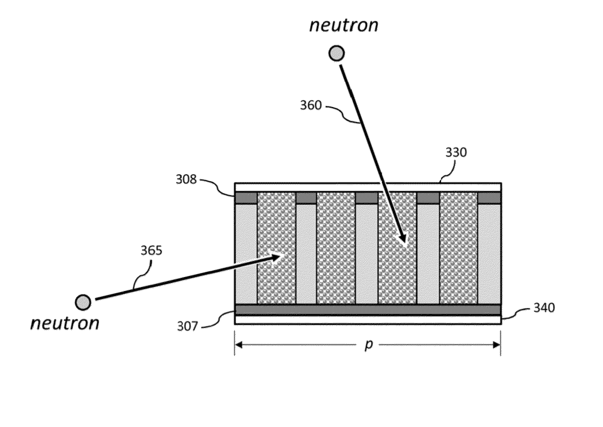
[0110]Turning now to FIG. 10A and FIG. 10B, a typical embodiment 1000 of this sensor is shown. FIG. 10B is a cross-sectional view, corresponding to an A-A sectioned cut of the fiber structure in FIG. 10A. The neutrons 1065 to be detected are typically incident in a direction normal to the long axis of the structure. This beam alignment is similar to that depicted in FIG. 3C and FIG. 4C, where a neutron beam (365 and 465, respectively) impinges upon the sensor from the side of the structure. The overall structure 1000 can be of lengths ranging from mm's to km's, and, can be of diameters in the range of mm's to cm's.

[0111]The basic structure is comprised of two classes of flexible, fiber-based components: (1) a central hollow fiber, loaded with neutron conversion nano-powder material 1030; and (2) an ensemble of optical fibers, each comprised of scintillation materials 1015, that are parallel to, and, surround the powder-loaded central fiber. An optical detector 1080, whose function i...

second embodiment

[0122]One can increase the accuracy with which the temporal correlation function is determined by modifying the optical fiber configuration with respect to the overall structure. Recall above, that a set of long fibers are placed along the length of the fiber, as shown in FIG. 10B. Therefore, the total fiber length is equal to the length of the powder-filled tube. However, in another embodiment, a single fiber (or a small set of fibers), can be wound around the powder-filled tube and along its length in a helical pattern, as in a spool. In this case, the total fiber length increases roughly by the number of fibers in the former embodiment. Therefore, the ability to determine the physical location of an event is enhanced, given that the temporal photon delay along the length of the tube is now dictated by the pitch of the helical pattern and the outside diameter of the fiber(s); and, not by the physical length of the tube. As an example, assuming a 1 mm (1000 μm) diameter powder-fill...


PUM


Abstract

Three-dimensional boron particle loaded thermal neutron detectors utilize neutron sensitive conversion materials in the form of nano-powders and micro-sized particles, as opposed to thin films, suspensions, paraffin, etc. More specifically, methods to infiltrate, intersperse and embed the neutron nano-powders to form two-dimensional and / or three-dimensional charge sensitive platforms are specified. The use of nano-powders enables conformal contact with the entire charge-collecting structure regardless of its shape or configuration.

Description

CROSS-REFERENCE TO RELATED APPLICATIONS[0001]This application claims the benefit of U.S. Provisional Patent Application No. 61 / 508,992 titled “Three-Dimensional Boron Particle Loaded Thermal Neutron Detector,” filed Jul. 18, 2011, incorporated herein by reference. This application is a Continuation in Part of U.S. patent application Ser. No. 13 / 014,879, titled “Method to Planarize Three-Dimensional Structures to Enable Conformal Electrodes,” filed Jan. 27, 2011, incorporated by reference. U.S. patent application Ser. No. 13 / 014,879 claims priority to U.S. provisional No. 61 / 509,023, filed Jul. 18, 2011, incorporated herein by reference. U.S. application Ser. No. 13 / 014,879 is a continuation-in-part of U.S. patent application Ser. No. 11 / 414,288, titled “Semiconductor Materials Matrix for Neutron Detection,” filed Apr. 27, 2006, incorporated herein by reference. U.S. patent application Ser. No. 11 / 414,288 claims priority to U.S. Provisional Patent Application Ser. No. 60 / 675,654, tit...

Claims


Application Information

Patent Timeline
IPC IPC(8): H01L31/08H01L31/18
CPCH01L31/085H01L31/115G01T3/08H01L31/18
Inventor NIKOLIC, REBECCA J.CONWAY, ADAM M.GRAFF, ROBERT T.KUNTZ, JOSHUA D.REINHARDT, CATHERINEVOSS, LARS F.CHEUNG, CHIN LIHEINECK, DANIEL
Owner LAWRENCE LIVERMORE NAT SECURITY LLC
Why Eureka
Try Eureka