
Alloy Depositing Machine And Method Of Depositing An Alloy Onto A Workpiece

a technology of alloy depositing machine and workpiece, which is applied in the direction of welding apparatus, manufacturing tools, and evacuating shielding, etc., can solve the problems of increasing the cost of specialty wires, increasing the cost of these specialty wires, and increasing was

Inactive Publication Date: 2012-12-27
CATERPILLAR INC
View PDF9 Cites 30 Cited by
  • Summary
  • Abstract
  • Description
  • Claims
  • Application Information

AI Technical Summary

Benefits of technology

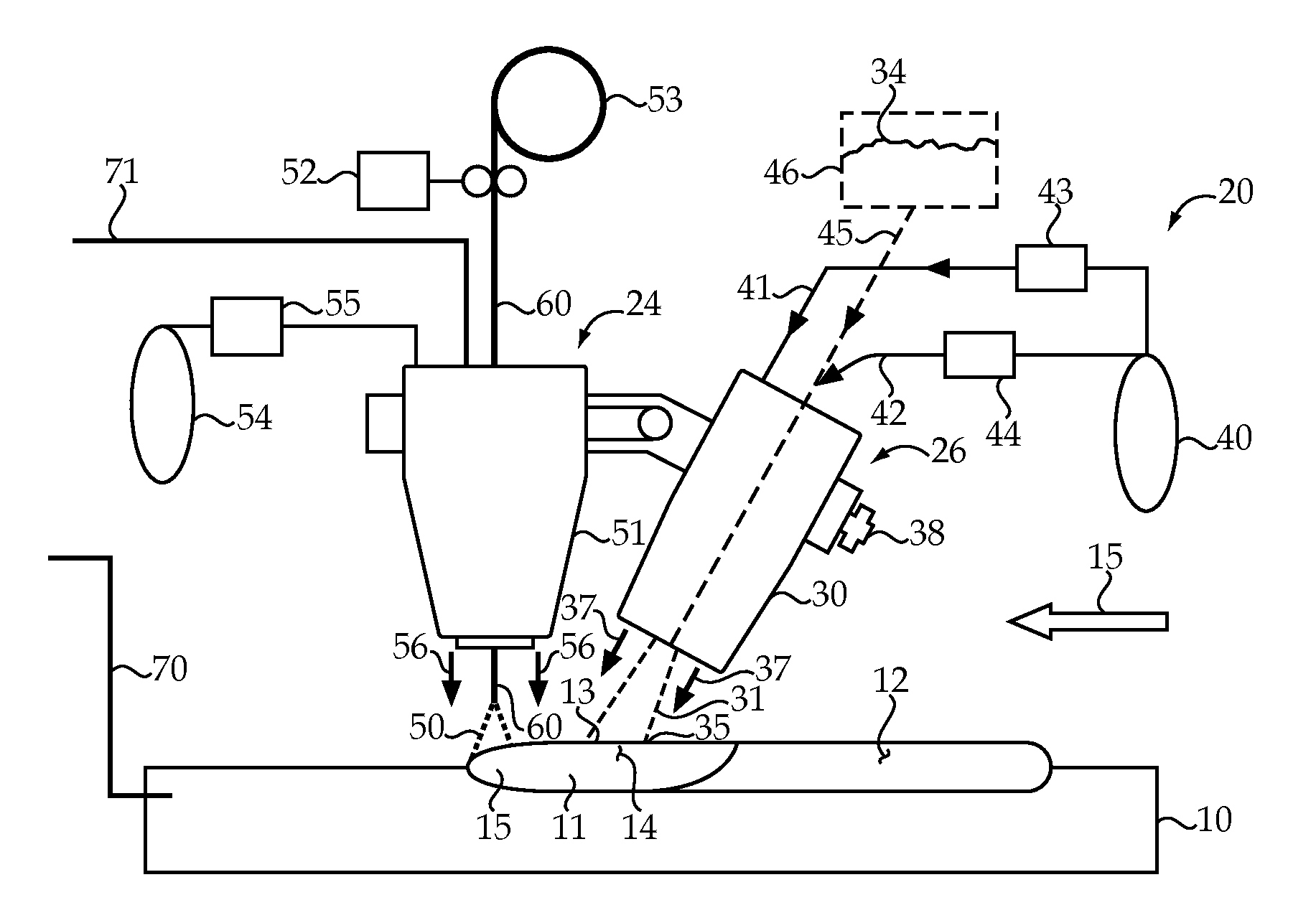
[0005]In one aspect, an alloy depositing machine is used for depositing an alloy onto a workpiece. The machine includes a workpiece support, welding unit and a powder alloy feeding system. The welding unit includes a wire feed system to supply wire to a welding head. The powder alloy feeding system includes a powder feed nozzle fluidly connected to an alloy powder supply. The welding head and powder feed nozzle move in a travel direction relative to the workpiece. The powder feed nozzle is positioned and oriented to feed a powder stream of alloy powder into a molten pool generated on the workpiece by the welding head at a low temperature location behind the ...

Problems solved by technology

The cost of these specialty wires can be significant.
In addition, waste can drive up costs because some or most of the desired alloy elements have vaporization temperatures that are lower than a temperature produced by the welding unit, which may be on the order of 5000-6000° C. For instance, manganese, cobalt aluminum and copper all boil at temperatures below 3000° C. Of the alloy elements mentioned, tungsten probably has the highest boiling temperature at around 5550° C. As a result, specialty wires often need to include surplus concentrations of certain alloy elements to account for an often sizable fraction of that element that is vaporized during the arc welding deposit procedure.
This problem becomes more acute as element costs increase.
In addition, because there are only a finite number of different specialty wires available, certain hard alloy deposit chemistries cannot be achieved without formulation of still more different specialty wires.
Thus, the current process involves substantial waste producing increased cost, and provides a limited number of alloy recipe combinations.

Method used


Image

  • Alloy Depositing Machine And Method Of Depositing An Alloy Onto A Workpiece
  • Alloy Depositing Machine And Method Of Depositing An Alloy Onto A Workpiece

Examples


Embodiment Construction

[0010]The present disclosure recognizes that various elements that are preferred in making hardfacing alloys have a variety of different melting and boiling temperatures, all of which may be below the hottest area associated with an electrical arc from an welding unit, which may be on the order of 5000-6000° C. The table below lists the melting and boiling temperatures for a variety of different elements that commonly form different portions of a hardfacing alloy. Nevertheless, elements not listed on the below table but utilized in a significant concentration in a hardfacing alloy (or welding alloy) would still fall within the scope of the present disclosure.

ElementT melting, ° C. (° F.)T boiling, ° C. (° F.)Manganese1250 (2280)2060 (3740)Silicon1410 (2570)3265 (5909)Molybdenum2617 (4742)4640 (8385)Carbon3600 (6512)4827 (8720)Chromium1857 (3374)2671 (4840)Vanadium1900 (3450)3400 (6152)Nickel1453 (2647)2900 (5252)Tungsten3407 (6164) 5550 (10022)Zirconium1852 (3365)4400 (7952)Boron230...


PUM

PropertyMeasurementUnit
Temperatureaaaaaaaaaa
Momentumaaaaaaaaaa
Flow rateaaaaaaaaaa

Abstract

A hardfacing machine is used for depositing a hardfacing alloy onto a metallic workpiece. An welding unit includes a wire feed system to supply wire to a welding head. A powder alloy feeding system includes a powder feed nozzle fluidly connected to an alloy powder supply. The welding head and powder feed nozzle move in a travel direction relative to the workpiece. The powder feed nozzle is positioned and oriented to feed a powder stream of alloy powder into a molten pool generated on the workpiece by an electrical arc produced by the welding head at a low temperature location behind the welding head relative to the travel direction. This alloy surfacing strategy limits vaporization of alloy elements by avoiding the high temperature region associated with the electrical arc.

Description

TECHNICAL FIELD[0001]The present disclosure relates generally to arc deposition of alloys onto metallic workpieces, and more particularly to an electrical arc machine that feeds a stream of alloy powder to a low temperature portion of a molten pool on the workpiece.BACKGROUND[0002]Applying hardfacing alloy deposits to metallic workpieces as a strategy to combat wear problems has been known for almost 100 years. Depending upon the type of wear to be resisted, many different alloy compositions have been identified. Broadly speaking, hardfacing is a process by which a coating is applied to a workpiece for the purpose of reducing wear or loss of material through abrasion, impact, erosion, gulling, cavitation or some combination of these wear types. At one extreme, iron based alloys are relatively low cost and easy to apply with a low alloy wire that includes significant amounts of carbon, and maybe other alloy elements including manganese and / or silicon. Various carbide alloys might inc...

Claims


Application Information

Patent Timeline
IPC IPC(8): B23K9/04
CPCB23K9/04B23K9/324B23K9/173B23K9/042
Inventor YELISTRATOV, ALEXEI
Owner CATERPILLAR INC
Learn More