
Forged roll meeting the requirements of the cold rolling industry and a method for production of such a roll

a cold rolling industry and forged roll technology, applied in the field of forged rolls and to production of forged rolls, can solve the problems of insufficient disclosure of parameters and properties of prior art pieces, and become more and more questionable, and achieve the effects of low friction coefficient, no dust pollution, and high roughness retention

Active Publication Date: 2012-09-06
AKERS INT AB
View PDF3 Cites 19 Cited by
  • Summary
  • Abstract
  • Description
  • Claims
  • Application Information

AI Technical Summary

Benefits of technology

[0013]The general object of the invention is to provide a roll and an industrial process for producing such a roll that is operative during the conditions in a cold rolling mill, preferably in a non-coated form. A more specific object is to provide such a roll and process for producing such a roll while keeping tribological properties such as low friction coefficient, high roughness retention, no dust pollution by iron fines at least equivalent to prior art coated rolls and which exhibit improved mill performances in terms of higher crack resistance and higher safety in operation compared to known rolls.
[0015]Improving the roll surface which gives the roll higher performance,
[0019]The solution to the problem, partial problems and aspects listed above is a roll according to the invention with improved fire crack resistance and low crack propagation which will reduce the sensitivity to mill incidents while keeping higher wear resistance.

Problems solved by technology

This practice is effective and efficient, but is becoming more and more questionable and in a near future unacceptable due to environmental restrictions.
Explosion of a roll can involve safety of operating persons and collateral damage in the mill.
However, these pieces of prior art lack the disclosure of parameters and properties necessary to achieve and enable such an HSS roll that is operative during the conditions in a cold rolling mill.

Method used


Image

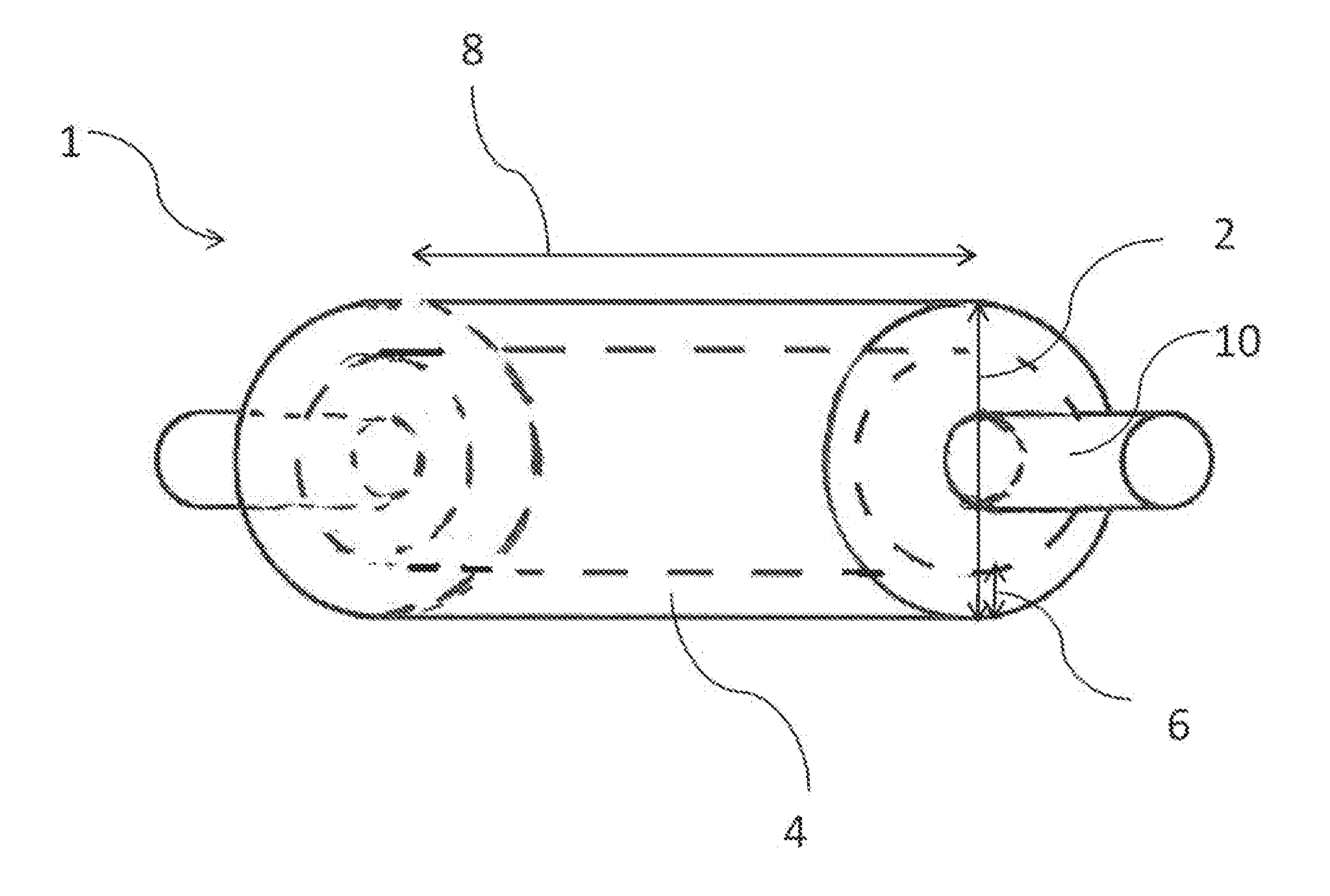
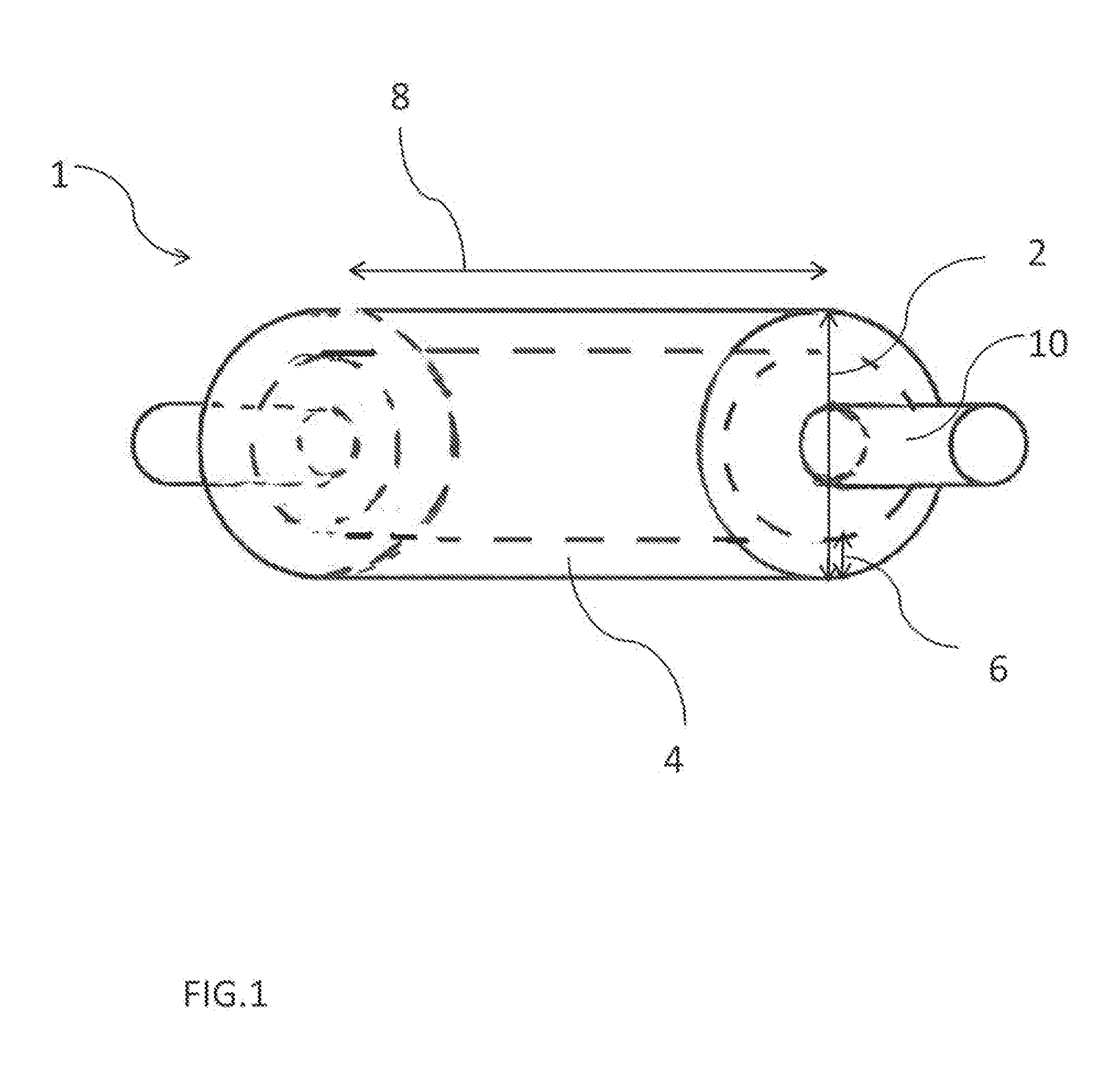
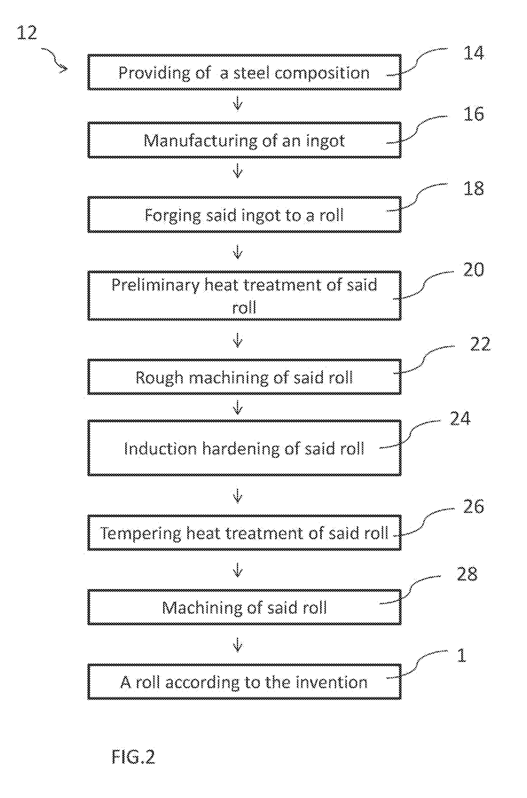
  • Forged roll meeting the requirements of the cold rolling industry and a method for production of such a roll
  • Forged roll meeting the requirements of the cold rolling industry and a method for production of such a roll
  • Forged roll meeting the requirements of the cold rolling industry and a method for production of such a roll

Examples


example 1

[0322]This example shows the effect on the microstructure in the roll according to the invention when using a solidification rate higher than 15° C. / min during formation of the ingot 34 according to the invention.

[0323]FIG. 5A-B show an example of a microstructure of INGOT 1 according to the invention which is made using a process with a solidification rate in average 50° C. / min (on 90 mm depth of the ingot) while cooling the ingot from 1400° C. to 1200° C. The eutectic cells in the example INGOT 1 according to the invention are small (940, 942), FIG. 5B shows the fragmented network with to an open eutectic network. See also FIG. 8 for the different solidification intervals in the different parts of the ingot during the solidification showing the temperature rate in the core 82, the mid-radius 84, 90 mm 86, 50 mm 88, 30 mm 90 and surface 92. FIG. 5B is a magnification of FIG. 5A. See also table 2.

[0324]FIG. 6A-B show an example of a microstructure of INGOT 2 according to the inventi...

example 2

[0326]This example shows the effect of using a solidification rate lower than 15° C. / min during formation of the TEST 1 ingot.

[0327]FIG. 7A-C show an example of a microstructure of the TEST1 ingot which is made using a process with a solidification rate of lower than 15 (in fact even lower than 10) ° C. / min while cooling the ingot in the solidification interval from 1400° C. to 1200° C. The cells 700 of the comparative TEST 1 ingot in FIG. 7A-C are larger in size, see for example cross section 708 which has a cross sectional length 708 is larger than the largest cross section in for example of the INGOT 1 in example 1 according to the invention. TEST 1 ingot also shows shrinkage porosities 704. The coarse conglomerate eutectic network 702 can also be seen in FIG. 7A-C. See also table 2. FIG. 7B-C is a magnification of FIG. 7A.

[0328]A solidification rate lower than 15″C / min within the solidification interval gives a high segregation of the carbides and a coarse carbide network 702 th...

example 3

[0334]This example shows an INGOT 1 microstructure produced according to the method of the invention by experimentation in the laboratory with controlled solidification device and controlled cooling speeds higher than 15° C. / min in the solidification interval. When a chemical composition comprising Mo in 1.4% is used according to the invention, an open eutectic carbide system 750 is achieved in the ingot structure, see FIG. 10A-B. See also table 3. This open eutectic carbide system 750 as is seen in the roll 1 according to the invention is characterized as a dendrite pattern and the eutectic carbide structures 752 is not forming closed eutectic carbides network (as in comparative example 4, TEST2) but instead forms dendrite arms in a network, see FIG. 10A-B which shows a picture of the microstructure of an ingot with 1.4% Mo is produced according to the process of the invention. This open eutectic carbide system according to the invention makes the roll easier to grind compared to r...


PUM

PropertyMeasurementUnit
Temperatureaaaaaaaaaa

Abstract

A forged roll for use, inter alia, in the cold rolling industry and a method of producing a forged roll as described. The roll has a steel composition, by weight, with 0.8 to less than 1% C, 0.2 to 0.5% Mn, 0.2 to 2.0% Si, 7.0 to 13.0% Cr, 0.6 to 1.6% Mo, more than 1.0 to 3.0% V, the remainder being Fe and impurities. The steel is tempered martensite with retained austenite at less than 5% per volume with eutectic carbides of less than 5% by volume, a hardness between 780-840 HV, and internal compressive stresses of between −300 to −500 MPa.

Description

FIELD OF INVENTION[0001]This invention relates in general to the field of forged rolls and to production of forged rolls. More particularly the present invention relates to forged rolls meeting the requirements of and mainly being directed for use in the cold rolling industry.DESCRIPTION OF THE RELATED ART[0002]The general trend for development in cold rolling both for the ferrous and the non-ferrous metal industries is to roll faster, thinner and wider. The current challenge is to do this while achieving perfect control of flatness, thickness and surface aspects compatible with a high productivity. Therefore, this trend calls for use of advanced rolling technologies that control key rolling parameters.[0003]Some key parameters such as roughness retention and surface aspects can be guaranteed through chrome plating of work rolls. This practice is effective and efficient, but is becoming more and more questionable and in a near future unacceptable due to environmental restrictions.[0...

Claims


Application Information

Patent Timeline
IPC IPC(8): B21B27/02C22C38/04C22C38/02C21D1/10C22C38/22
CPCC22C38/22C21D2211/008C21D2211/004C21D1/22C22C38/02C22C38/24C22C38/04C21D1/18C21D1/10Y02P10/25
Inventor GASPARD, CLAUDEVERGNE, CATHERINEBATAZZI, DANIEL
Owner AKERS INT AB
Learn More