Reflective anode electrode for organic el display

a technology of anode electrode and organic el, which is applied in the direction of solid-state devices, diaphragms, metallic material coating processes, etc., can solve the problems of increasing the number of tfts, increasing the influence of such obstacles, and low contact resistance, and achieving high reflectance. , the effect of low contact resistan

Inactive Publication Date: 2012-08-09
KOBE STEEL LTD
View PDF2 Cites 10 Cited by
  • Summary
  • Abstract
  • Description
  • Claims
  • Application Information

AI Technical Summary

Benefits of technology

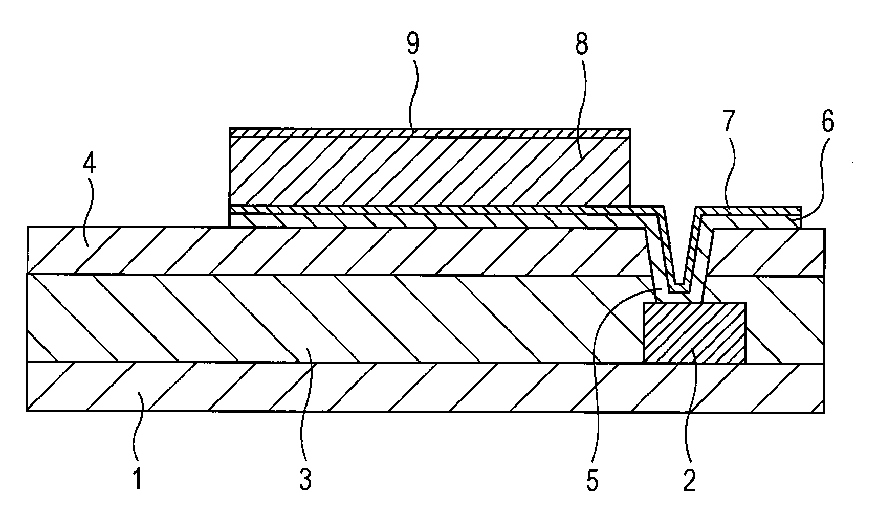
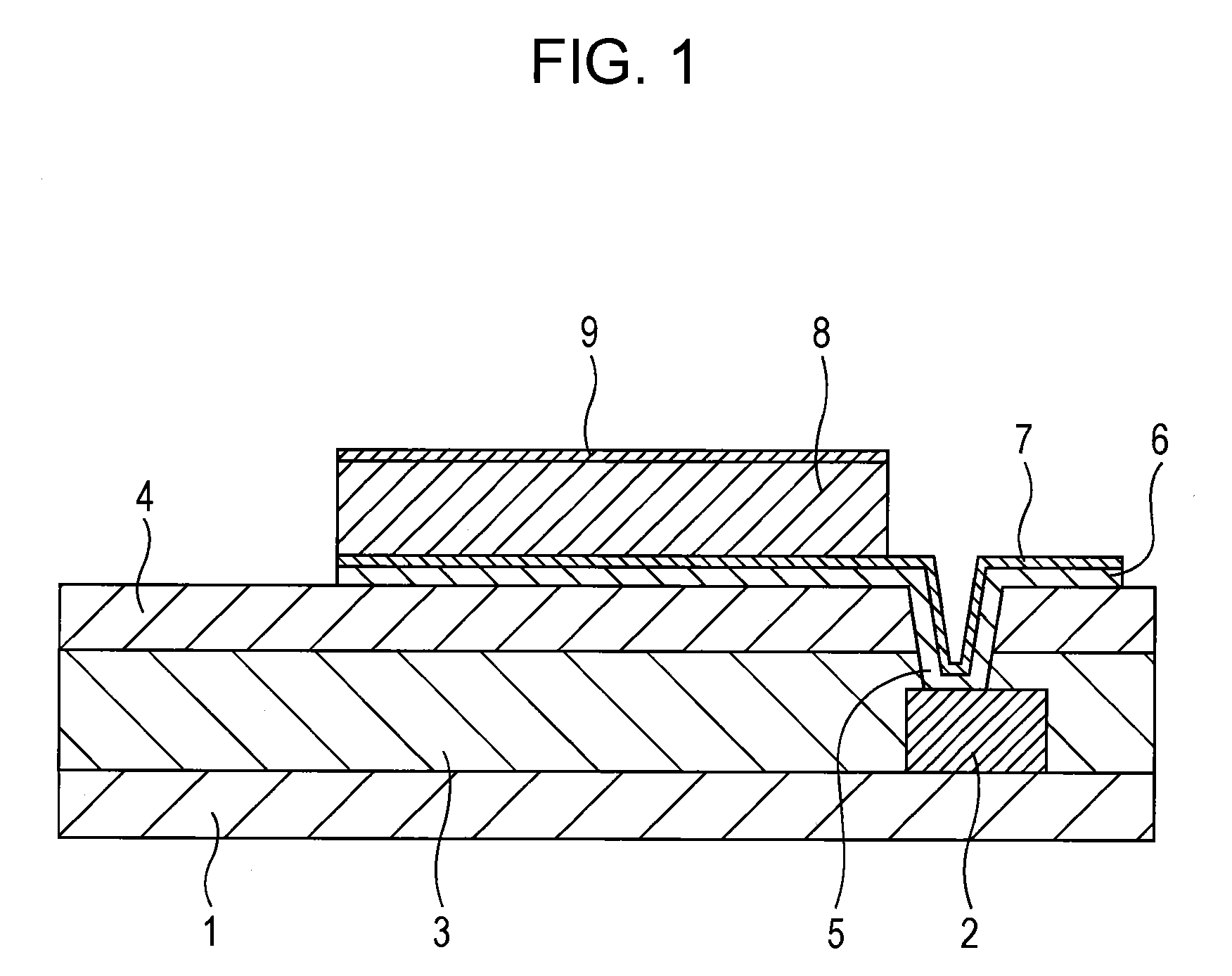
[0030]According to the invention, an Al-Ag alloy film containing a specific amount of Ag is used as an Al-based alloy reflective film. With this configuration, even a direct contact of the film with an oxide conductive film such as ITO or IZO ensures a low contact resistance and a high reflectance, and the multilayer structure having the reflective film and the oxide conductive film (upper layer=oxide conductive film / lower layer=Al-based alloy) exhibits a work function of the surface of the upper oxide conductive film that is as high as the work function of the surface of an upper oxide conductive film in a general multilayer structure having an Ag-based alloy film and the oxide conductive film (upper layer=oxide conductive film / lower layer=Ag-based alloy). The reflective anode electrode according to the invention enables holes to be injected efficiently into an organic emitting layer, and can efficiently reflect the light emitted from the organic emitting layer by the reflective film. Thus, the inventive reflective anode electrode enables an organic EL display to exhibit excellent emission brightness properties.
[0031]Further, the Al-based alloy reflective film may contain Ag and a specific amount of at least one element selected from La, Ce, Nd, Y, Sm, Ge, Gd and Cu (hereinafter, sometimes collectively referred to as X). The use of such an Al—Ag—X alloy film results in a reflective anode electrode for organic EL display which is increased in terms of resistance to alkali corrosion and resistance to heat.

Problems solved by technology

Passive-type devices have a simple structure but are not suited for a full color display.
The influence of such obstacles increases as the drive circuits become more complicated and the number of TFTs is increased.
Although an upper negative electrode (cathode) needs to be formed of a transparent conductive film, ITO is not suited for electron injection because of its high work function.
Further, sputtering or ion beam deposition of ITO into a film causes the risk that an electron transport layer (an organic material which forms organic EL devices) will be damaged by plasma ions or secondary electrons during the film formation.
Although an Ag-based alloy is poor in corrosion resistance, this inherent problem is solved by coating the Ag-based alloy film with an ITO film that is stacked on the alloy film.
However, Ag is an expensive material and upsizing of a sputtering target which is necessary for film production is difficult.
Because of these problems, it is difficult to use an Ag-based alloy film as a reflective film in an active matrix-type, top-emission organic EL display for constituting a large-screen TV.
However, a direct contact of an Al reflective film with an oxide conductive film such as ITO or IZO results in a high contact resistance so as to make it impossible to supply a current enough to inject holes into the organic EL devices.
However, such a remedy causes a great deterioration in reflectance, resulting in a decrease in emission brightness that is a display characteristic.

Method used


Image

  • Reflective anode electrode for organic el display
  • Reflective anode electrode for organic el display

Examples


example 1

[0084]In this example, various kinds of Al alloy reflective films were used and studies were made in order to examine how performing no heat treatment (Group A, Table 1) or performing post-annealing (Group B, Table 2) would affect the work function, the reflectance and the electrical resistivity, as well as the heat resistance, which is a property achieved according to a preferred embodiment of the invention.

[0085]First, an alkali-free glass plate (plate thickness: 0.7 mm) as a substrate was provided, and a SiN passivation film (film thickness: 300 nm) was formed on the surface of the substrate with a plasma CVD apparatus. The film production conditions were substrate temperature: 280° C., gas ratio: SiH4 / NH3 / N2=125 / 6 / 185, pressure: 137 Pa, and RF power: 100 W. On the surface of the passivation film, an Al alloy film which was a reflective film (film thickness: about 100 nm) was formed by a sputtering method. The compositions of the Al alloy films are described in Tables 1 and 2. Th...

example 2

[0108]In this example, Al alloy reflective films having the same compositions as in EXAMPLE 1 were used and studies were made in order to examine how performing pre-annealing and alkaline solution treatment (Group C, Table 3) or performing pre-annealing, alkaline solution treatment and post-annealing (Group D, Table 4) would affect the work function, the reflectance, the electrical resistivity and the contact resistance, as well as the heat resistance and the alkali corrosion resistance, which are properties achieved according to a preferred embodiment of the invention.

[0109]First, reflective films were produced in the same manner as described in EXAMPLE 1. The produced reflective films were grouped into Group C and Group D. The films belonging to Group C were heat treated (pre-annealed) at 250° C. for 30 minutes in a nitrogen atmosphere and were thereafter subjected to an alkaline solution treatment (a TMAH treatment) in which the films were soaked in an alkaline solution that was ...

example 3

[0120]In this example, the influence of the thickness of ITO film on the reflectance was studied.

[0121]In detail, reflective films were produced in the same manner as described in EXAMPLE 1, grouped into Group A and Group B, and treated in the same manner as described in EXAMPLE 1. The thickness of the ITO film was varied from 5 to 50 nm by changing the sputtering time. For comparison, similar processing was performed using a pure Al film or an Al-0.6% by atom Nd which was a simulated alloy film according to PTL 1.

[0122]The reflective anode electrodes manufactured as described above were tested in the same manner as described in EXAMPLE 1 in order to evaluate the reflectance. The results are described in Tables 5 and 6.

TABLE 5Composition ofITO filmPost-Reflect-No.reflective film*Groupthicknessannealingance1Pure AlA 5 nmNoA2Pure AlA10 nmNoA3Pure AlA30 nmNoB4Pure AlA50 nmNoC5Al—0.6NdA 5 nmNoA6Al—0.6NdA10 nmNoA7Al—0.6NdA30 nmNoB8Al—0.6NdA50 nmNoC9Al—0.6AgA 5 nmNoA10Al—0.6AgA10 nmNoA11A...


PUM

PropertyMeasurementUnit
thicknessaaaaaaaaaa
thicknessaaaaaaaaaa
thicknessaaaaaaaaaa

Abstract

Disclosed is a reflective anode electrode for an organic EL display, which comprises a novel Al-based alloy reflective film. The reflective anode electrode is capable of assuring low contact resistance and high reflectance even in cases where the Al reflective film is in direct contact with an oxide conductive film such as an ITO or IZO film. In addition, when the Al reflective film is formed into a laminated structure together with the oxide conductive film, the work function of the surface of the upper oxide conductive film is equally high with the work function of a laminated structure that is composed of a general-purpose Ag-based alloy film and an oxide conductive film. Specifically disclosed is a reflective anode electrode for an organic EL display, which is formed on a substrate and characterized by comprising a laminated structure that is composed of an Al-based alloy film containing 0.1-6% by atom of Ag and an oxide conductive film that is formed on the Al-based alloy film so as to be in direct contact with the Al-based alloy film.

Description

TECHNICAL FIELD[0001]The present invention relates to a reflective anode electrode for use in an organic EL display (in particular, a top-emission organic electroluminescent display).BACKGROUND ART[0002]An organic electroluminescent (hereinafter, referred to as “organic EL”) display, which is a type of self-luminous flat panel display, is an all solid state flat panel display in which organic EL devices are arranged in a matrix configuration on a substrate such as a glass plate. In an organic EL display, positive electrodes (anodes) and negative electrodes (cathodes) are formed in stripe shapes, and intersections of these electrodes form pixels (organic EL devices). When a current is passed through such organic EL devices by the application of a voltage of several V from an external power supply, the organic molecules are excited to an excited state. The atom then returns to the ground state (the stable state), releasing extra energy in the form of light having a color that is inher...

Claims


Application Information

Patent Timeline
Patent Type & Authority Applications(United States)
IPC IPC(8): H01L51/54C23C14/14H01L23/48
CPCC22C21/00C23C14/185C23C14/3414H05B33/28H01L51/5271H05B33/26H01L51/5218H10K59/80518H10K59/878Y10S428/917H10K50/818H10K50/856
Inventor IWANARI, YUMIKUGIMIYA, TOSHIHIROHIRANO, TAKAYUKIMAEDA, TAKEAKI
Owner KOBE STEEL LTD
Why Eureka
Try Eureka