Eureka AIR delivers breakthrough ideas for toughest innovation challenges, trusted by R&D personnel around the world.

Resonant Vacuum Arc Discharge Apparatus for Nuclear Fusion

a vacuum arc discharge and nuclear fusion technology, applied in nuclear reactors, nuclear engineering, greenhouse gas reduction, etc., can solve the problems of requiring leakage to replenish ions lost, limited life of tubes in this embodiment, etc., and achieve high melting point, poor absorber of hydrogen isotopes, and high efficiency of fusion reactions.

Inactive Publication Date: 2012-01-12
FLEMING RAY R
View PDF6 Cites 18 Cited by
  • Summary
  • Abstract
  • Description
  • Claims
  • Application Information

AI Technical Summary

Benefits of technology

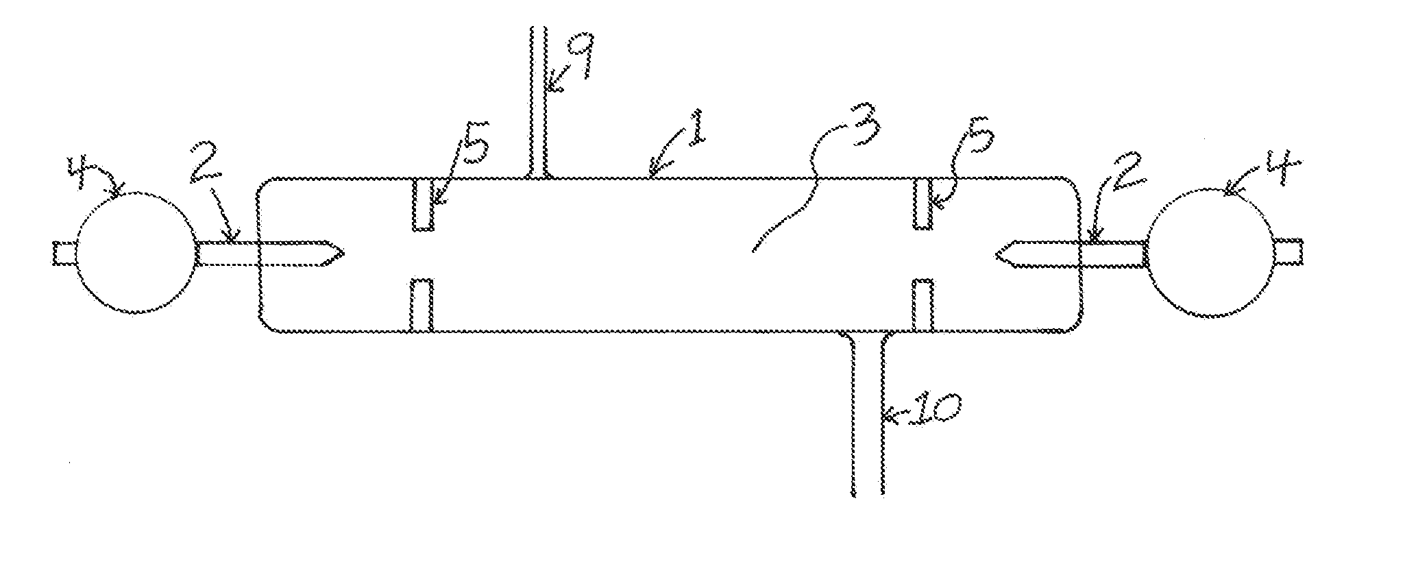
[0028]The operation of this fusion apparatus is similar in many ways to the most modern designs for fluorescent lamps, neon lights, or flash lamps, except that the vapor pressure is much lower and the voltage much higher. To improve the efficiency while reducing size and cost of the power supply, the present invention incorporates high-frequency resonant inverter technology into the supply with the addition of a high-frequency high-voltage transformer. In order to achieve fusion efficiently, a power supply must be used that is capable of delivering hundreds of watts of power at a hundred kilovolts or more.
[0030]The electrode material used is also important to the invention. Target density is critical to achieving high efficiency with fusion reactions. While tungsten is a popular choice for cold cathode lamps or x-ray tubes due to its high melting point it is a poor absorber of hydrogen isotopes. To improve fusion efficiency, an electrode comprised of a material that is an excellent hydrogen isotope absorber is a preferred embodiment. Palladium, scandium, and titanium are three of the best elements for that purpose, with palladium being the best performer and titanium a good lower cost option. The hydrogen density of hydrated palladium can approach that of liquefied hydrogen. Fusion techniques relying on plasmas can never approach those target densities.
[0031]Improved electrode shape is another important embodiment of the invention. Most cold cathode lamps use conically shaped electrodes. The tips of these electrodes melt and vaporize and become rounded as a result of repeated arcing. As the tips become more rounded, higher voltage is required to sustain the arcs. Tip rounding also spreads out the fusion target area reducing the probability of fusion events occurring. In the preferred embodiment the invention incorporates hollow electrodes. They are thin enough to remain consistently sharp at the edge as they vaporize so the arcing voltage remains more consistent. Hollow electrodes also present a smaller target area and more consistent cross section so the rate of fusion is greater and stays constant. Hollow electrode vacuum arc discharge systems have been shown experimentally to have a higher light and x-ray output than solid electrodes for a given energy input. This improved efficiency is also realized when hollow electrodes are used for fusion.
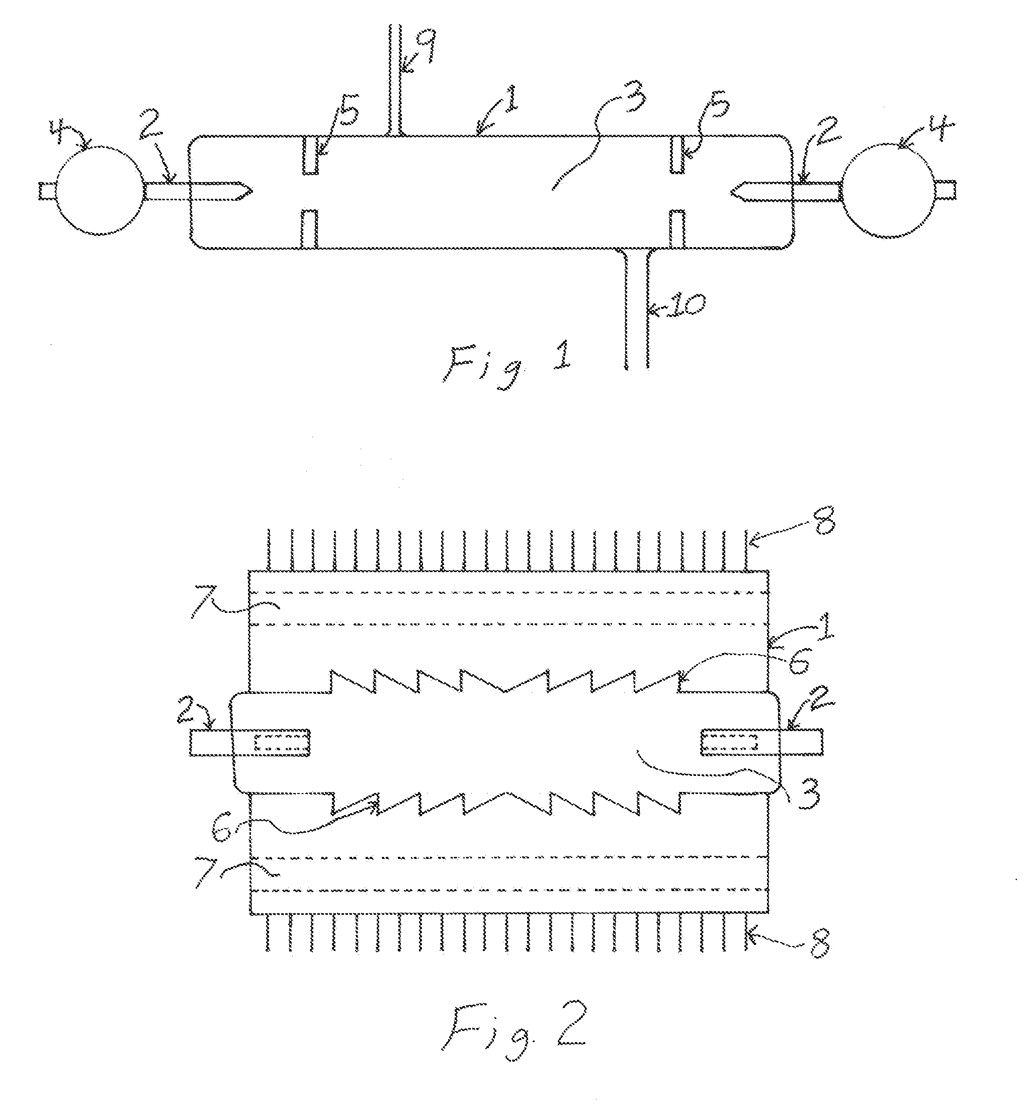
[0032]Enhanced tube envelope material and design is another aspect to the invention. Modifications from a basic cylindrical tube shape can improve longevity and heat transfer. One of the failure modes of an accelerator tube fusion device is that vaporized electrode material plates out along the tube body forming a ground path. The tube can be designed with corrugations or rings to break up the electrical continuity of the plated areas and thereby extend tube life. The envelope designed can include fins on the outside to increase surface area for more rapid heat transfer. The envelope will also function as an electrical insulator to prevent the tube from being electrically grounded. An important embodiment of this invention with respect to energy generation is that a tube must have proper electrical insulation so it can be immersed directly in water, or other heat transfer fluid so that both heat due to fusion and waste heat can be used for electrical production.
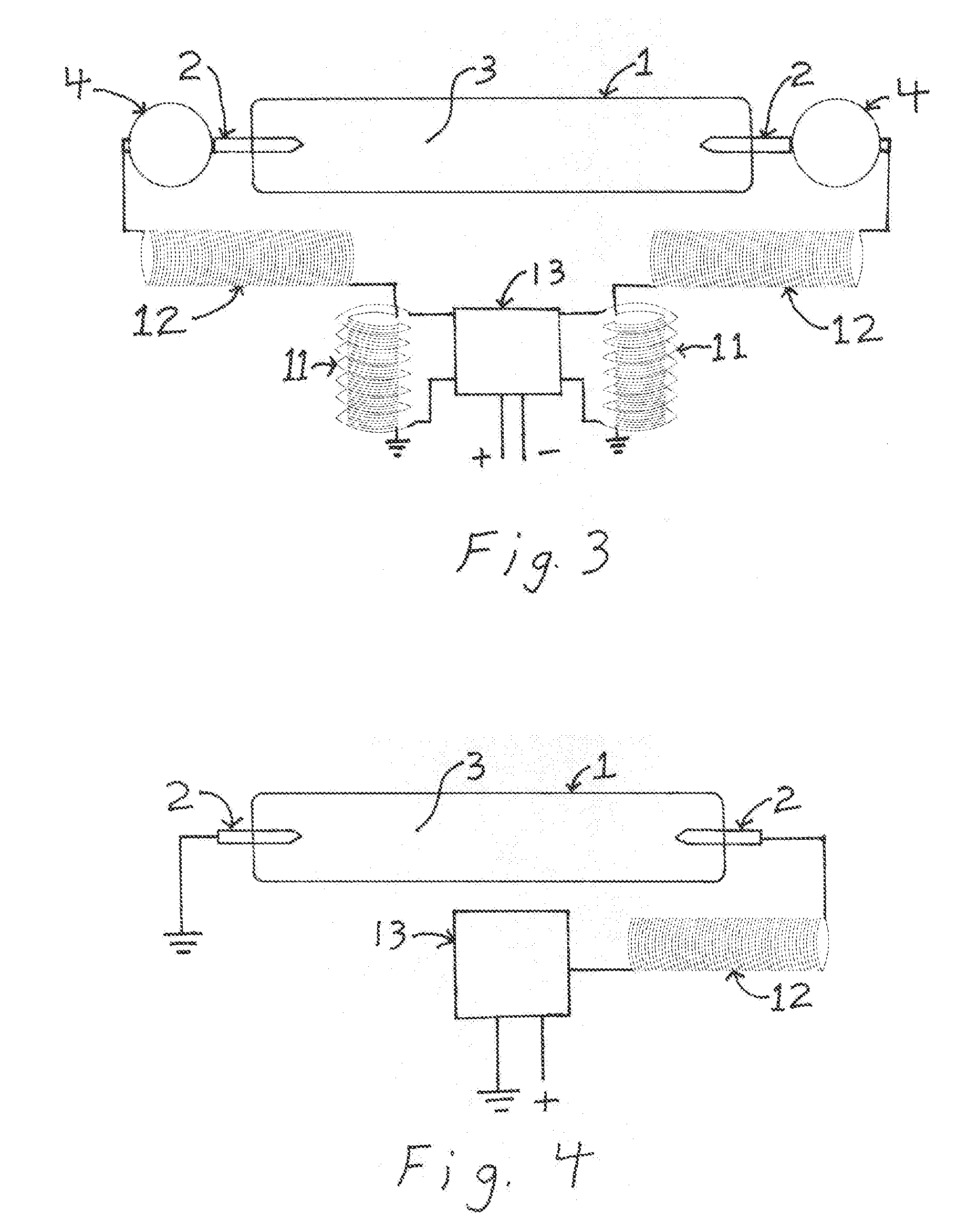
[0033]The use of a resonant AC power supply is perhaps the most important aspect to the invention. The greatest gains can be achieved by using AC rather than the DC typically used in a fusion accelerator tube. Keeping in mind that the ions are accelerated at near light speed, the vapor in a tube is accelerated in less than a few of nanoseconds. AC operation produces arcs in alternate directions that shut down between pulses. The more rapidly the arcs are quenched and the magnetic field collapses, the more energetic the pulses generated and greater the fusion output produced. As the number or arcs per second increases, the output increases. If the coil or coils connected to the tube can be made to resonate, then unconverted energy can be stored and passed back through the tube multiple times further improving efficiency.
[0034]The embodiment of the resonant power supply is a designed where the stage of the high-voltage power supply between the high-frequency inverter and the fusion tube is a resonant RLC (Resistance-Inductance-Capacitance) circuit. These circuits can be very efficient with almost all the energy going into the inverter being available for arc production. In the preferred embodiment of the invention, high-voltage resonator coils along with some additional capacitance are placed on opposite sides of the arc path so that arcs can resonate back and forth at very high frequency independent of the inverter or transformer.

Problems solved by technology

If a vacuum system is used to maintain constant pressure, a leak is required to replenish the ions lost.
However, the life of the tube in this embodiment is more limited.

Method used


Image

  • Resonant Vacuum Arc Discharge Apparatus for Nuclear Fusion
  • Resonant Vacuum Arc Discharge Apparatus for Nuclear Fusion
  • Resonant Vacuum Arc Discharge Apparatus for Nuclear Fusion

Examples


Embodiment Construction

[0041]The present inventions now will be described more fully hereinafter with reference to the accompanying drawings, in which some examples of the embodiments of the inventions are shown. Indeed, these inventions may be embodied in many different forms and should not be construed as limited to the embodiments set forth herein; rather, these embodiments are provided by way of example so that this disclosure will satisfy applicable legal requirements. Like numbers refer to like elements throughout.

[0042]The device in accordance with an embodiment of the present invention as illustrated in FIG. 4 consists of a high frequency inverter (13), a resonant coil (12), and a fusion tube comprising of an envelope (1), two electrodes (2) and vapor (3). The high frequency inverter produces alternating current (AC) from a direct current (DC) source. The DC voltage will generally be in the 400 volt to 4000 volt range, with the upper range increasing as high-voltage inverter technology improves. T...


PUM


Abstract

The present invention relates to a resonant vacuum arc discharge apparatus for producing nuclear fusion. A resonant high-frequency high-voltage alternating current (AC) power supply is used to efficiently power a fusion tube normally containing deuterium, tritium and / or helium-3 vapor. Metals that can hold large amounts of hydrogen isotopes such as palladium and titanium can be used to increase the target density. The nuclear fusion device can be used for energy production, well logging, uranium mining, neutron activation analysis, isotope production or other applications that require a neutron source.

Description

CROSS-REFERENCE[0001]There are no related patent applicationsSTATEMENT REGARDING FEDERALLY SPONSORED RESEARCH[0002]All development of the enclosed invention was conducted at the inventor's expense with no government assistance.PARTIES TO THE INVENTION[0003]The inventor, Ray R. Fleming possesses all rights to the invention.BACKGROUND OF THE INVENTION[0004]Energy production by nuclear fusion would be one of the most important developments in science, but the development of the technology has been much slower than hoped. In the mean time neutrons produced by smaller fusion accelerators are being used for such things as well logging of oil and gas wells, uranium mining, neutron activation analysis and potentially radioisotope production. All of these fields could use a more energy efficient means of achieving fusion.[0005]The first deuterium (D) fuel fusion device was reported by Oliphant and Rutherford in 1934. It was little different from the accelerators of today. It had a high volta...

Claims


Application Information

Patent Timeline
Patent Type & Authority Applications(United States)
IPC IPC(8): G21B1/00
CPCY02E30/18G21B3/00Y02E30/10
Inventor FLEMING, RAY R.
Owner FLEMING RAY R
Why Eureka
Eureka Blog
Learn More