Method for the Removal of Surface Oxides by Electron Attachment
a surface oxide and electron attachment technology, applied in the direction of metal-working equipment, non-electric welding equipment, solid-state devices, etc., can solve the problems of limiting the application of this approach, flammability of pure hydrogen, and drawbacks of the approach
- Summary
- Abstract
- Description
- Claims
- Application Information
AI Technical Summary
Problems solved by technology
Method used
Image
Examples
example 1
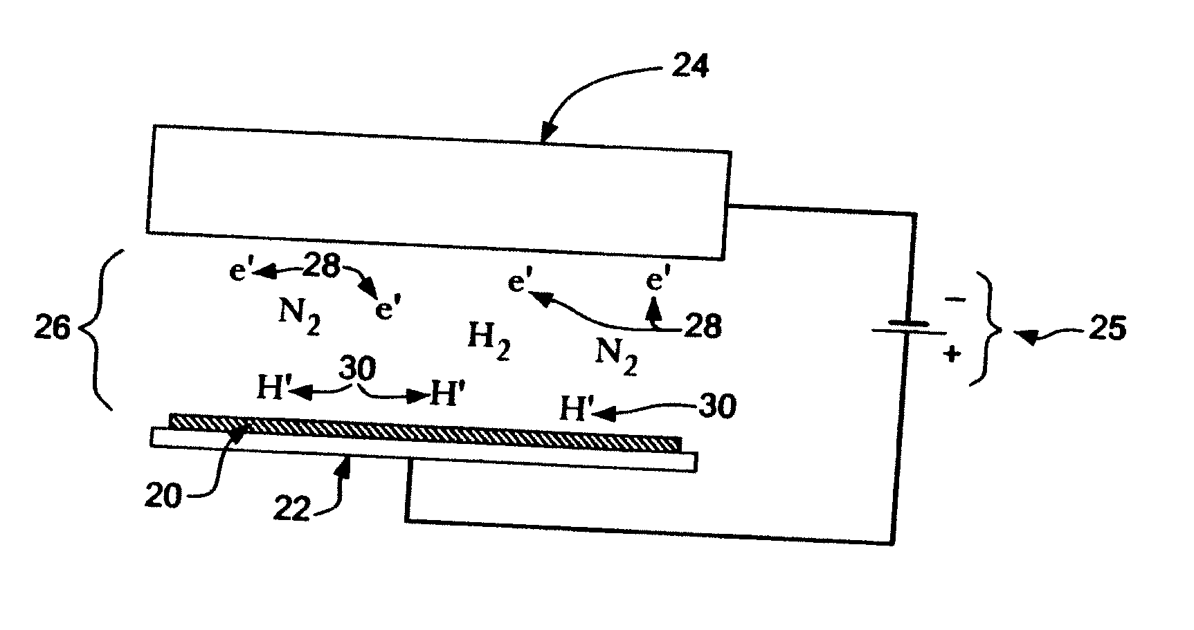
[0101]A first experiment was conducted by using a lab-scale furnace. The sample used was a fluxless tin-lead solder preform (melting point 183° C.) on a grounded copper plate (anode), which was loaded inside a furnace and heated up to 250° C. under a gas flow of 5% H2 in N2. When the sample temperature was at equilibrium, a DC voltage was applied between the negative electrode (cathode) and the grounded sample (anode) and gradually increased to about −2 kV with a current of 0.3 mA. The distance between the two electrodes was about 1 cm. The pressure was ambient, atmospheric pressure. It was found that the solder was indeed very well wetted on the copper surface. Without applying an electric voltage, a good wetting of a fluxless solder on a copper surface can never be achieved at such low temperature, even in pure H2, because the effective temperature for pure H2 to remove tin-oxides on a tin-based solder is above 350° C. Therefore, this result confirms that the electron-attachment m...
example 2
[0102]Several cathode materials were investigated for electron-attachment assisted hydrogen fluxless soldering by using the field emission mechanism using the same set-up as Example 1. The results of the investigation is provided in Table I.
[0103]As Table I illustrates, the best result was obtained by using a Ni / Cr cathode, which provided the highest fluxing efficiency and thus resulted in the shortest wetting time. It is believed that the Ni / Cr cathode generates a relatively larger quantity of electrons and has suitable energy level of the electrons compared to other cathode materials.
TABLE IEffect of Cathode Material on Wetting Time at 250° C. and 20% H2Material of Cathode RodTime towith a Sharp Tip ( 1 / 16″ dia.)Complete WettingBrass1 min 55 secCopper1 min 44 secNickel Chromium39 secAluminum1 min 28 secStainless Steel1 minTungsten1 min 54 sec
example 3
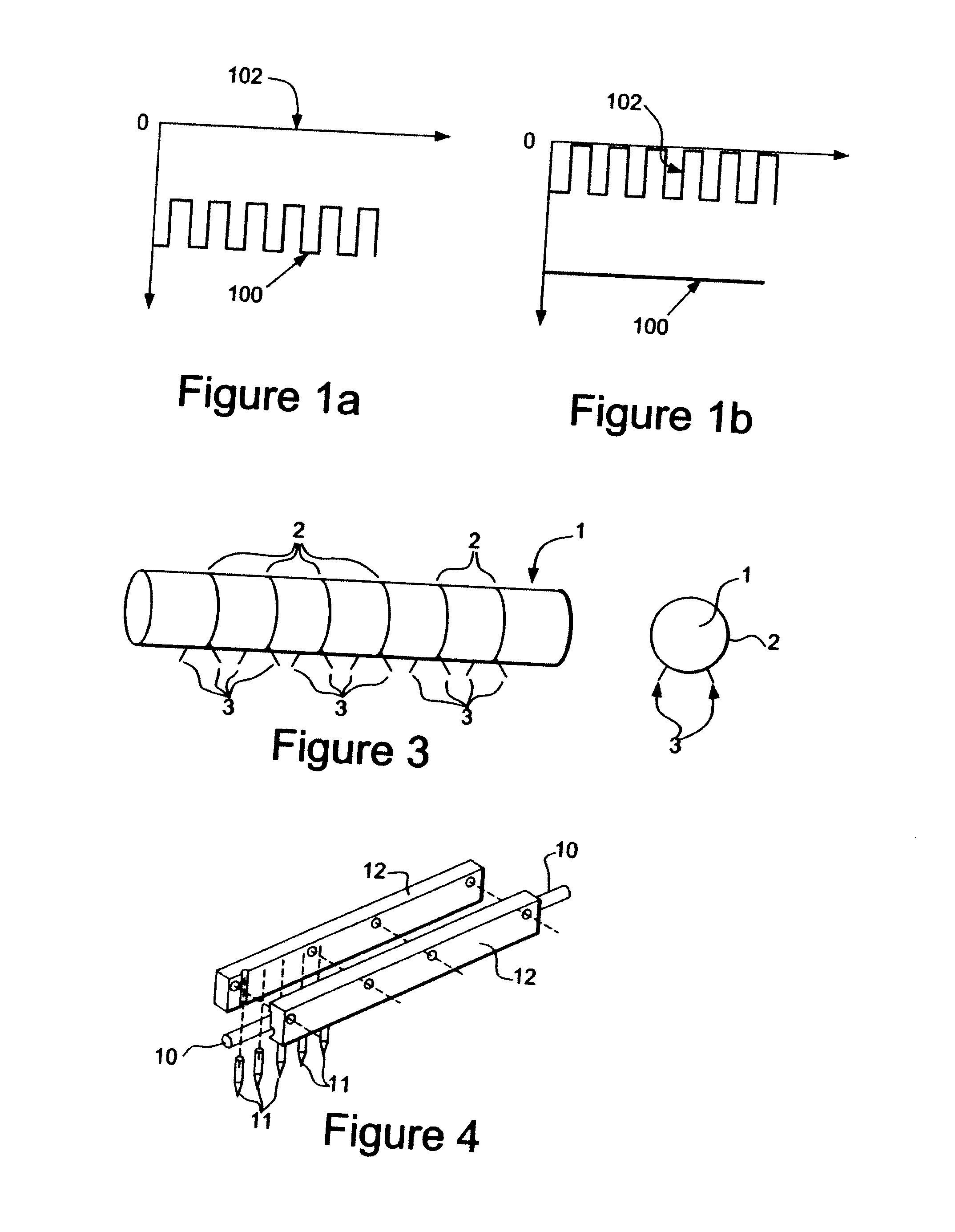
[0104]The present example was conducted to investigate the effectiveness of the thermal-field emission method for generating electrons. A 3 mm diameter graphite rod, having a number of 1 mm long machined tips protruding from its surface, acted as the cathode and had a geometry similar to that depicted in FIG. 2i. Each of the protruding machined tips had a tip angle of 25 degrees. The graphite rod was heated up in a gas mixture of 5% H2 and 95% N2 to about 400 to 500° C. by resistive heating using an AC power source. A DC voltage source of 5 KV was applied between the graphite cathode and a copper plate that acted as an anode having a 1.5 cm gap therebetween. All the tips on the graphite rod were illuminated thereby indicating that electrons could uniformly be generated from the distributed tips on the graphite rod. Without heating of the graphite rod, there would be either no electron emission from the cathode, or arcing between one of the tips and the anode plate. This demonstrates...
PUM
| Property | Measurement | Unit |
|---|---|---|
| temperature | aaaaa | aaaaa |
| distance | aaaaa | aaaaa |
| voltage | aaaaa | aaaaa |
Abstract
Description
Claims
Application Information
 - R&D
- Intellectual Property
- Life Sciences
- Materials
- Tech Scout
- Unparalleled Data Quality
- Higher Quality Content
- 60% Fewer Hallucinations
Browse by: Latest US Patents, China's latest patents, Technical Efficacy Thesaurus, Application Domain, Technology Topic, Popular Technical Reports.
© 2025 PatSnap. All rights reserved.Legal|Privacy policy|Modern Slavery Act Transparency Statement|Sitemap|About US| Contact US: help@patsnap.com


