
Core material of carrier for electrophotographic developer and method for manufacturing the core material, carrier and method for manufacturing the carrier, and electrophotographic developer using the carrier

Inactive Publication Date: 2011-01-20
POWDERTECH
View PDF3 Cites 8 Cited by
  • Summary
  • Abstract
  • Description
  • Claims
  • Application Information

AI Technical Summary

Benefits of technology

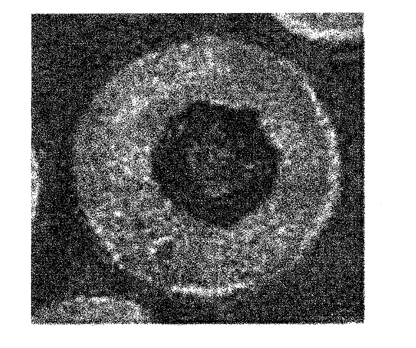
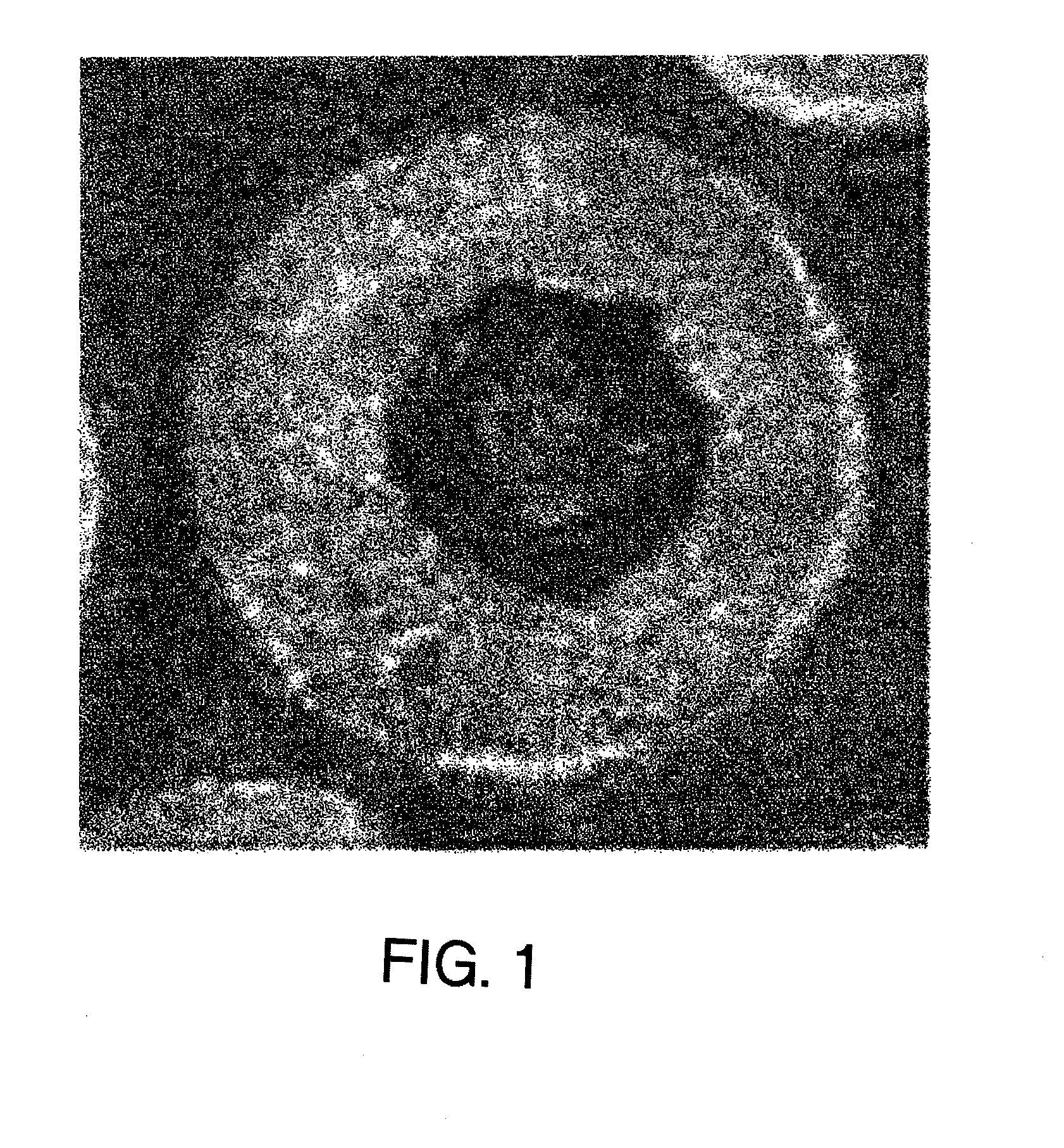
[0042]The carrier core material for an electrophotographic developer according to the present invention comprises 3 to 100% by number, preferably 3 to 60% by number and more preferably 3 to 40% by number of a hollow particle having an iron content of 36 to 78% by weight. The case where the iron content is less than 36% by weight means that the iron is not a main component. The iron content cannot be higher than 78% by weight because an iron oxide containing the largest amount of iron is FeO. when the hollow particles account for less than 3% by number, the core material does not differ from usual core material particles containing no hollow particle, not providing the advantage of the present invention. The proportion of hollow particles is determined as the number of hollow particles contained in one visual field / the number of all particles contained in the one visual field by photographing the cross-sections of the core material particles by SEM at a magnitude of 200 times. The content of Fe and the contents of Mg and Ti described later were measured as follows.
[0043]0.2 g of a carrier core material was weighed; the carrier core material was added to a solution in which 20 ml of hydrochloric acid at 1 mol / l and 20 ml of nitric acid at 1 mol / l were added to 60 ml of pure water, and heated to prepare an aqueous solution in which the carrier core material was completely dissolved; and the contents of Fe, Mg and Ti were measured using an ICP analyzer (ICPS-1000IV, made by Shimadzu Corp.).
[0044]The carrier core material for an electrophotographic developer according to the present invention desirably has an average particle diameter of 20 to 150 μm, more desirably 20 to 100 μm, and most desirably 25 to 100 μm. A carrier core material having an average particle diameter less than 20 μm is very difficult to produce by the manufacturing method according to the present invention. A carrier using a particle having an average particle diameter larger than 150 μm as a carrier core material for an electrophotographic developer leads to a bad image quality, which is not preferable. The average particle diameter was measured as follows.(Average Particle Diameter)
[0045]The average particle diameter was measured by a laser diffraction scattering method. A measuring apparatus used was a MicroTrack Particle Size Analyzer (Model: 9320-X100), made by Nikkiso Co., Ltd. The measurement was conducted at a refractive index of 2.42 and under environments of 25±5° C. and a humidity of 55±15%. The average particle diameter (median diameter) used here refers to a cumulative 50% particle diameter in the volume distribution mode and of sieve undersize indication. Dispersion of a carrier sample was carried out by using a 0.2% sodium hexametaphosphate aqueous solution as a dispersion liquid and subjecting the carrier sample to an ultrasonic treatment for 1 min by an Ultrasonic Homogenizer (UH-3C), made by Ultrasonic Engineering Co., Ltd.
[0046]The carrier core material for an electrophotographic developer according to the present invention desirably has a true specific gravity of 2.5 to 4.75 g / cm3, more desirably 3.5 to 4.75 g / cm3, and most desirably 3.8 to 4.75 g / cm3. A carrier core material having a true specific gravity higher than 4.75 g / cm3 does not differ from usual core material particles, not providing the advantage of the present invention. In the case where the true specific gravity is lower than 2.5 g / cm3, even if hollow particles are produced, since the strength of the particles is inferior, the particles cannot be used as a carrier core material for an electrophotographic developer. The true specific gravity was measured as follows.(True Specific Gravity)
[0047]The true specific gravity was measured using a pycnometer according to JIS R9301-2-1. A solvent used was methanol, and the measurement was conducted at a temperature of 25° C.

Problems solved by technology

However, since such an iron powder carrier has a true specific gravity as heavy as about 7.8 and a too high magnetization, agitation and mixing thereof with a toner particle in a development box is liable to generate fusing of toner-constituting components on the iron powder carrier surface, so-called toner spent.
Such generation of toner spent reduces an effective carrier surface area, and is liable to decrease the frictional chargeability of a toner particle.
In a resin-coated iron powder carrier, a resin on the surface is peeled off due to stress during the durable period and a core material (iron powder) having a high conductivity and a low dielectric breakdown voltage is exposed, thereby causing the leakage of the charge in some cases.
Such leakage of the charge causes the breakage of electrostatic latent images formed on a photoreceptor and the generation of brush streaks on solid portions, thus hardly providing uniform images.
However, such a method for manufacturing a ferrite carrier has various problems.
Specifically, since the sintering step as a step of causing the magnetization by a ferritization reaction generally uses a tunnel kiln, and raw materials are filled in a saggar and sintered, the shape of the ferrite carrier is liable to be deformed due to the influence among the ferrite particles, more remarkably especially in ferrite particles having smaller particle diameters, and after the sintering, the ferrite particles turn into blocks and generate cracks and chips on disintegration thereof, resulting in mingling of deformed particles.
Moreover, in the case of manufacturing a ferrite particle having a small particle diameter, a ferrite particle having a good shape cannot be provided without intensified crushing.
There is further a problem that the sintering time, if including the temperature-raising time, the maximum temperature-holding time and the temperature-descending time, needs about 12 hours, and the particles having turned into blocks after the sintering need to be disintegrated, resulting in poor production stability.
Further, since a carrier core material manufactured by such a sintering method has not only cracked and chipped particles but also many deformed particles, even if a resin film is formed, a uniform film is difficult to form.
The portions having a thin resin film exhibit early exposure of the carrier core material due to stress, and causes the leakage phenomenon and the broadening of the charge amount distribution, thereby making the long-term stabilization of high-quality images difficult.
However, in this case, the surface of the particles become porous, and the rising-up of charging becomes worse due to the infiltration of a resin and the like; and the resin amount in unnecessarily infiltrated portions becomes large, which is economically inferior; thus, this case is not preferable from both viewpoints of quality and cost.
However, this manufacturing method is carried out in a ratio of the oxygen amount / the combustion gas amount of 3 or less, which makes the sintering difficult depending on ferrite raw materials.
Further, the method is not suitable for manufacture of a ferrite having a small particle diameter, for example, about 20 to 50 μm, meeting the recent years' particle diameter reduction of carriers, and cannot provide spherical uniform ferrite particles.
The hollow particle is obtained without a thermal treatment such as sintering, but hollow particles of several to several tens of micrometers cannot be obtained.
Further, the document contends that its application is, for example, a use as a carbon dioxide-fixing catalyst obtained by wash coating the hollow particle on a honeycomb carrier having a monolithic structure, and drying the coated carrier, and as required, sintering it, and thus the hollow particle cannot be used as a carrier core material for an electrophotographic developer.
By the method of controlling the apparent density and / or the true specific gravity by forming pores in such a way, it is very difficult to obtain a spherical smooth surface.
Although use of an additive having a low specific gravity allows control of the apparent density and the true specific gravity, since the additive is present in the interior and on the surface of the particle, there arises an apprehension that the additive influences characteristics of the particle.
Particularly, the chargeability of a negatively charging toner by the particle manufactured by the method disclosed in Patent Document 5 is remarkably bad due to negative chargeability of the silica contained therein.
Patent Documents 3 to 5 cited above disclose hollow particles, but methods disclosed therein need the previous addition of a substance to form hollows, causing a problem that the substance is liable to remain depending on the sintering condition.

Method used


Image

  • Core material of carrier for electrophotographic developer and method for manufacturing the core material, carrier and method for manufacturing the carrier, and electrophotographic developer using the carrier
  • Core material of carrier for electrophotographic developer and method for manufacturing the core material, carrier and method for manufacturing the carrier, and electrophotographic developer using the carrier

Examples


example 1

[0114]FeOOH was used as a raw material of a carrier core material; water, a binder component and a dispersant were added thereto such that the solid content became 50%; and the mixture was pulverized for 2 hours by a bead mill, and thereafter granulated by a spray drier. The binder used was PVA, and a 10%-PVA aqueous solution was added such that PVA became 1.0% by weight of the whole solid content. The obtained granulated material was passed at a feed rate of 40 kg / hr through a flame to which propane at 5 Nm3 / hr and oxygen at 25 Nm3 / hr were fed, to obtain a regularly sintered material. The obtained sintered material was classified and magnetically sorted to obtain a carrier core material having an average particle diameter of 38.23 μm and containing hollow particles. The feeding of the granulated material to the flame was carried out by an air flow conveyance using nitrogen gas, and the feeding rate of the nitrogen gas flow was set at 11.5 Nm3 / hr.

example 2

[0115]A carrier core material having an average particle diameter of 37.61 μm and containing hollow particles was obtained by the same manner as in Example 1, except that FeOOH and TiO2 as raw materials of the carrier core material were weighed in a molar ratio of 2 moles and 1 mole, respectively.

example 3

[0116]A carrier core material having an average particle diameter of 38.45 μm and containing hollow particles was obtained by the same manner as in Example 1, except that FeOOH, Mg(OH)2 and TiO2 as raw materials of the carrier core material were weighed in a molar ratio of 16.5 moles, 3.5 moles and 2.5 moles, respectively.


PUM


Abstract

Objects of the present invention are to provide a carrier core material for an electrophotographic developer having a true spherical shape and excellent strength, and a controllable true density and / or apparent density, and a method for manufacturing the carrier core material, a carrier and a method for manufacturing the carrier, and an electrophotographic developer using the carrier. In order to achieve the objects, there are employed a carrier core material for an electrophotographic developer, containing 3 to 100% by number of hollow particles having an iron content of 36 to 78% by weight, and a carrier for an electrophotographic developer, obtained by coating a resin on a surface of the carrier core material, and methods for manufacturing these, and an electrophotographic developer using the carrier.

Description

TECHNICAL FIELD[0001]The present invention relates to a core material of a carrier for an electrophotographic developer used for a two-component electrophotographic developer used in copying machines, printers and the like and a method for manufacturing the core material, a carrier and a method for manufacturing the carrier, and an electrophotographic developer using the carrier.BACKGROUND ART[0002]The method of electrophotographic development is a method in which toner particles in a developer are made to adhere to electrostatic latent images formed on a photoreceptor to develop the images. The developer used in this method is classified into a two-component developer composed of a toner particle and a carrier particle, and a one-component developer using a toner particle above.[0003]As a development method using a two-component developer composed of a toner particle and a carrier particle among those developers, a cascade method and the like were formerly employed, but a magnetic ...

Claims


Application Information

Patent Timeline
IPC IPC(8): G03G15/08G03G9/10G03G9/107G03G9/113
CPCG03G9/1075G03G9/1132G03G9/1131
Inventor AGA, KOJISHINMURA, ISSEIIGARASHI, TETSUYA
Owner POWDERTECH
Learn More