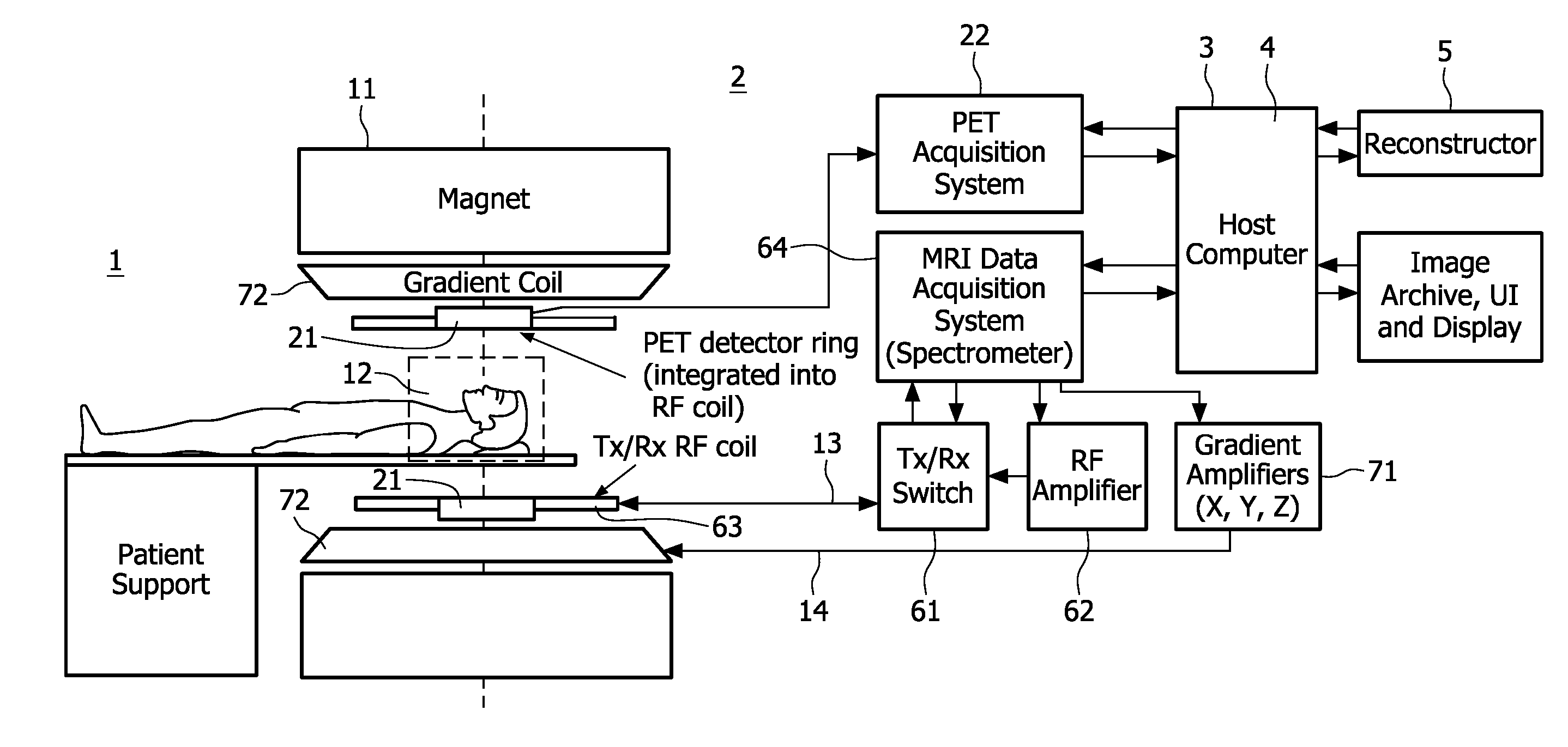
[0012]The acquisition of both the nuclear decay signals and the magnetic resonance signals is controlled by a
system controller that is common to the emission tomography system and the magnetic resonance examination system. The common
system controller enables to link the nuclear decay signals and the magnetic resonance signals in that a definite relationship between nuclear decay signals and magnetic resonance signals is established. That is, the motion information contained in the magnetic resonance signals is equal to motion that affects the nuclear decay signals. This relationship between the magnetic resonance signals and the nuclear decay signals enables that motion derived from the magnetic resonance signals can be applied to reconstruct the motion corrected emission
tomographic image. The
motion correction may be performed by applying the motion correction to the acquired nuclear decay signals and then reconstruct the motion corrected emission
tomographic image from the corrected nuclear decay signals. Alternatively, a primary emission tomographic image can be reconstructed from the acquired nuclear decay signals and then apply the motion correction to the primary emission tomographic image to produce the motion corrected emission tomography image.
[0014]According to one aspect of the invention, the time of acquisition, i.e. the instant or temporal position of the time interval is registered at which or during which the nuclear decay signals and the magnetic resonance signals, respectively, are acquired. This time registration of the acquisition of the nuclear decay signals and the magnetic resonance signals can be achieved for example by simultaneously acquiring corresponding nuclear decay signals and magnetic resonance signals or by effecting a time-stamp to both the nuclear decay signals and the magnetic resonance signals. Thus, the motion correction derived from the magnetic resonance signals can be applied to the nuclear decay signals that were acquired at the same instant. Accordingly, the motion correction derived from the magnetic resonance signals pertains to the same motion that affected the nuclear decay signals and accurate motion correction of the motion corrected emission tomographic image is achieved. It is convenient to implement the time registration function in the
system controller.
[0015]The nuclear decay signals are often generated by administering a radiopharmaceutical to the patient to be examined. Upon administration, the radiopharmaceutical will radioactively decay from within the body of the patient and cause the emission of radioactive
radiation (usually gamma
radiation) from the body of the patient to be examined. Because nuclear decay signals can be acquired from the instant of administering the radiopharmaceutical, triggering the acquisition of the nuclear decay signals and magnetic resonance signals provides a
time efficient acquisition of nuclear decay signals having a relatively high
signal level.
[0018]
Motion correction is accurate and without the need for a high computational effort on the basis of redundancy of MR data in the centre region of k-space. Namely, most relevant motion occurs on a spatially coarse scale, i.e. involving sizes much larger than the fine details of the patient's
anatomy. Accordingly, larger scale structures and their motion are represented by magnetic resonance signals in the centre region of k-space. On the other hand fine details of structures are represented by magnetic resonance signals from the
peripheral region of k-space. The size of the centre region in which redundancy is generated may be selected by the user on the basis of the required accuracy of the motion correction and the acceptable
time duration of the acquisition of the magnetic resonance signals. Very good results are achieved by the so-called
PROPELLER acquisition sequence. The
PROPELLER acquisition sequence per se is discussed in detail in ‘
Motion correction with
PROPELLER MRI: Application to Head Motion and Free-
breathing Cardiac Imaging’ in MRM42(1999)963-969 by James G.
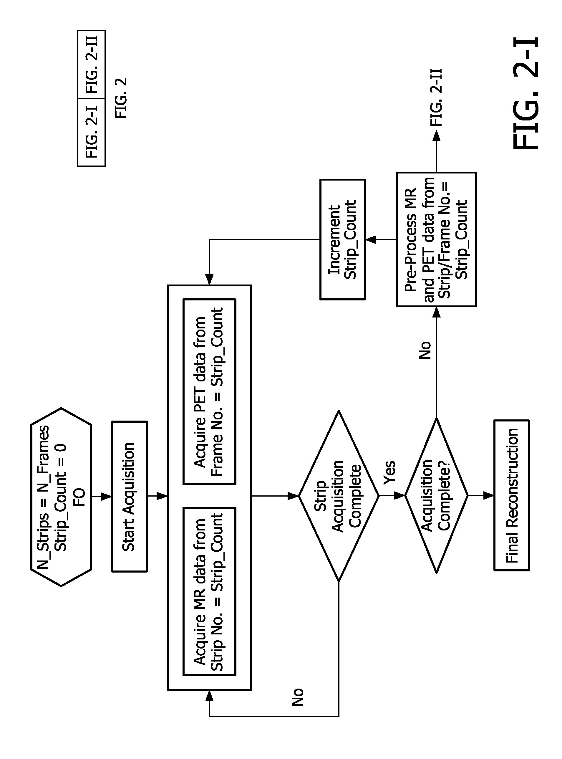
Pipe. In this paper motion correction of the magnetic resonance image itself reconstructed from the acquired magnetic resonance signals is discussed. The PROPELLER method scans k-space along rectangular planar (i.e. in a plane or
thin slab in k-space) strips that are successively rotated about the origin of k-space. This 2D acquisition may be repeated for successive planes in k-space. This approach requires a relatively short
acquisition time. Alternatively, a truly three-dimensional k-space acquisition may be carried out by applying a phase-encoding in the k-space direction transverse to the rotating plane or
thin slab. Another truly three-dimensional k-space acquisition involves to rotate a column or bar-shaped volume that contains the origin of k-space about two e.g. orthogonal axes in k-space simultaneously. Accordingly the
central region of k-space is sampled for successive individual strips. The
central region is in this implementation formed by the overlap of the successive individual strips and the size of the
central region is defined by the width of the strips or column or bar-shaped volume in k-space and the differences between the orientations of the strips in k-space. The redundancy of the magnetic resonance signals sampled from the control region of k-space allows notably to correct spatial inconsistencies in position, rotation and phase. Also the redundancy allows to reject data affected by through-plane motion. Further, the redundancy allows averaging which decreases artefacts for low spatial frequencies in the motion corrected magnetic resonance images. Because the PROPELLER acquisition sequence is cyclic in nature, continued acquisition of magnetic resonance signals is possible by performing multiple rotations of the strip(s) in k-space. Continued acquisition of the magnetic resonance signals allows to increase the
signal-to-
noise ratio of the ultimately reconstructed magnetic resonance image. Continued acquisition of nuclear decay signals achieves improvement of both the
signal-to-
noise ratio as well as the spatial resolution of the reconstructed emission tomography image.


