Eureka AIR delivers breakthrough ideas for toughest innovation challenges, trusted by R&D personnel around the world.

Image pickup lens, image pickup apparatus, and mobile terminal

A camera lens and subject image technology, applied in image communication, equipment, television, etc., can solve problems such as difficult to cope with the high pixel of the camera element, inability to ensure performance, insufficient aberration correction, etc.

Active Publication Date: 2010-09-01
KONICA MINOLTA INC
View PDF6 Cites 114 Cited by
  • Summary
  • Abstract
  • Description
  • Claims
  • Application Information

AI Technical Summary

Problems solved by technology

[0007] However, in the imaging lens described in the above-mentioned Patent Document 1, since the first lens to the third lens bear almost the refractive power of the entire system, the fourth lens and the fifth lens have only weak refractive power as image plane correction lenses. Therefore, the correction of aberration is not sufficient, and when the total length of the lens is shortened, there is a problem that it is difficult to cope with the increase in pixels of the imaging element due to performance degradation.
[0008] In addition, in the imaging lens described in Patent Document 2, since the front group composed of the first lens and the second lens is composed of a spherical system, correction of spherical aberration and coma aberration is insufficient and good performance cannot be ensured.
In addition, since the front group and the rear group after the third lens all have a positive refractive power structure, the main point of the optical system is different from a telephoto type structure in which the rear group has a negative refractive power. The position becomes the image side and the back focus becomes longer, so it is a type that is not conducive to miniaturization

Method used


Image

  • Image pickup lens, image pickup apparatus, and mobile terminal
  • Image pickup lens, image pickup apparatus, and mobile terminal
  • Image pickup lens, image pickup apparatus, and mobile terminal

Examples


Embodiment 1

[0182] The lens data of the imaging lens of Example 1 are shown below (Table 1).

[0183] Table 1

[0184] Example 1

[0185] f=5.35mm fB=0.35mm F=2.88 2Y=7.056mm

[0186] ENTP=0.83mm EXTP=-2.85mm H1=-2.77mm H2=-5mm

[0187] Surface No. R(mm) D(mm) Nd vd Effective Radius(mm)

[0188] 1* 1.868 0.99 1.54470 56.2 1.27

[0189] 2* -12.867 0.03 0.94

[0190] 3 (stop) ∞ 0.07 0.78

[0191] 4* -77.808 0.30 1.63200 23.4 0.78

[0192] 5* 3.130 0.52 0.87

[0193] 6* -7.802 0.49 1.63200 23.4 1.13

[0194] 7* -5.364 0.45 1.37

[0195] 8* -3.734 0.89 1.54470 56.2 1.63

[0196] 9* -1.726 0.67 1.94

[0197] 10* -3.739 0.50 1.54470 56.2 2.62

[0198] 11* 3.354 0.60 3.02

[0199] 12 ∞ 0.15 1.51630 64.1 3.56

[0200] 13 ∞ 3.60

[0201] Aspheric coefficient

[0202] Side 1 Side 7

[0203] K=0.86114E-01 K=0.29935E+01

[0204] A4=-0.36919E-02 A4=-0.22578E-01

[0205] A6=-0.11430E-02 A6=0.30410E-02

[0206] A8=-0.29234E-02 A8=0.21938E-02

[02...

Embodiment 2

[0243] The lens data of the imaging lens of Example 2 are shown below (Table 2).

[0244] Table 2

[0245] Example 2

[0246] f=5.54mm fB=0.66mm F=2.88 2Y=7.056mm

[0247] ENTP=0.82mm EXTP=-2.97mm H1=-2.09mm H2=-4.88mm

[0248] Surface No. R(mm) D(mm) Nd vd Effective Radius(mm)

[0249] 1* 1.720 0.96 1.54470 56.2 1.25

[0250] 2* -23.558 0.03 0.95

[0251] 3 (stop) ∞ 0.07 0.80

[0252] 4* 47.467 0.30 1.63200 23.4 0.82

[0253] 5* 2.945 0.61 0.87

[0254] 6* -6.119 0.64 1.63200 23.4 1.07

[0255] 7* -5.324 0.36 1.48

[0256] 8* -1.991 0.68 1.54470 56.2 1.66

[0257] 9* -1.322 0.45 1.94

[0258] 10* -14.605 0.50 1.54470 56.2 2.67

[0259] 11* 2.385 0.60 2.92

[0260] 12 ∞ 0.15 1.51630 64.1 3.46

[0261] 13 ∞ 3.51

[0262] Aspheric coefficient

[0263] Side 1 Side 7

[0264] K=0.53402E-01 K=0.11434E+02

[0265] A4=-0.45821E-02 A4=-0.19137E-01

[0266] A6=-0.41569E-02 A6=-0.95346E-02

[0267] A8=-0.31982E-02 A8=0.45815E-02

...

Embodiment 3

[0307] The lens data of the imaging lens of Example 3 are shown below (Table 3).

[0308] table 3

[0309] Example 3

[0310] f=4.81mm fB=0.5mm F=2.88 2Y=7.056mm

[0311] ENTP=0.66mm EXTP=-2.66mm H1=-1.84mm H2=-4.31mm

[0312] Surface No. R(mm) D(mm) Nd vd Effective Radius(mm)

[0313] 1* 1.792 0.78 1.54470 56.2 1.10

[0314] 2* 57.549 0.05 0.78

[0315] 3 (stop) ∞ 0.05 0.71

[0316] 4* 15.461 0.30 1.63200 23.4 0.75

[0317] 5* 2.544 0.41 0.86

[0318] 6* 6.186 0.36 1.63200 23.4 1.16

[0319] 7* 8.531 0.64 1.35

[0320] 8* -9.117 1.06 1.54470 56.2 1.94

[0321] 9* -1.182 0.40 2.19

[0322] 10* -2.455 0.45 1.54470 56.2 2.87

[0323] 11* 2.057 0.56 3.21

[0324] 12 ∞ 0.15 1.51630 64.1 3.49

[0325] 13 ∞ 3.53

[0326] Aspheric coefficient

[0327] side 1

[0328] K=0.28280E+00 The 7th side K=-0.19178E+02

[0329] A4=0.18157E-02 A4=-0.43032E-01

[0330]A6=0.36321E-02 A6=-0.10803E-02

[0331] A8=0.25085E-02 A8=-0.18993E-02

[0332] ...


PUM


Abstract

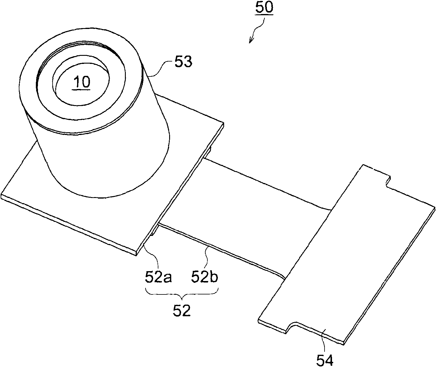
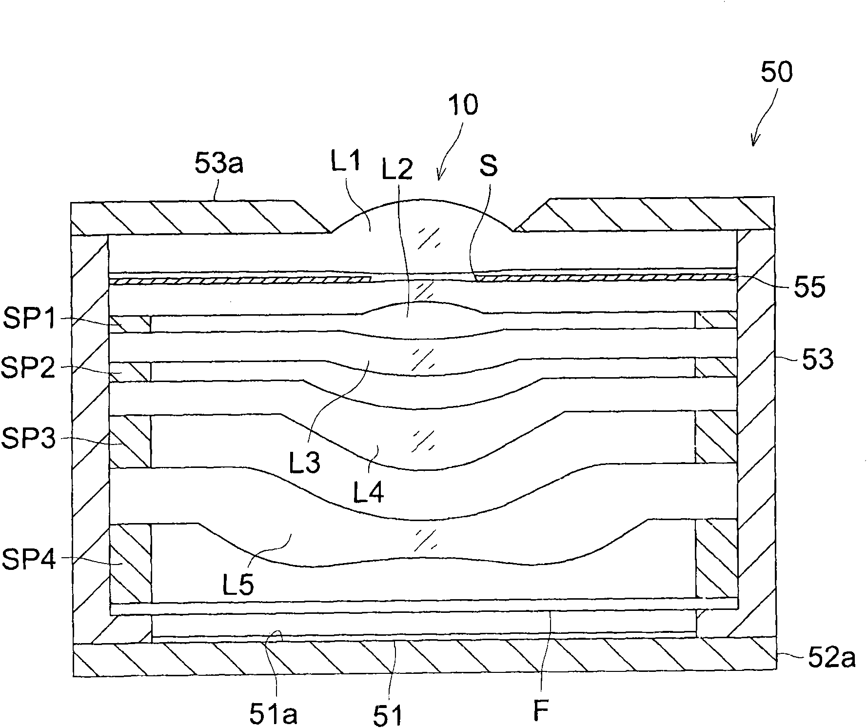
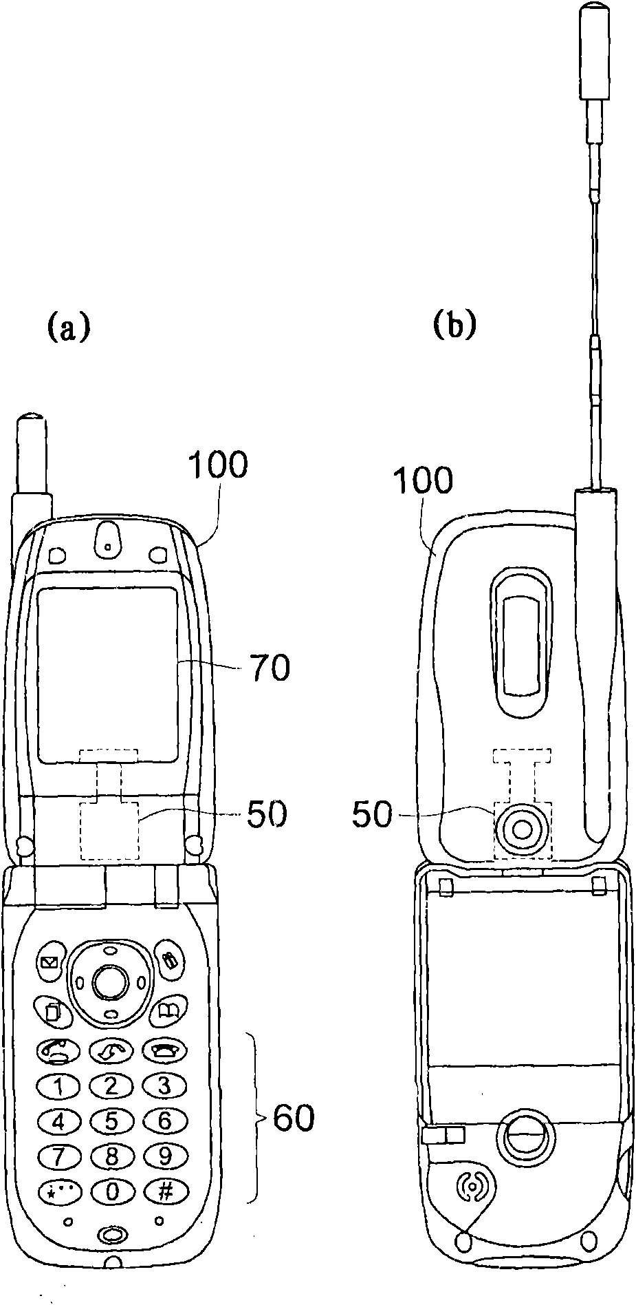
The present invention relates to an image pickup lens suitable for a small-sized image pickup apparatus and to an image pickup apparatus and a mobile terminal. An image pickup lens relating to the present invention is provided for forming an image of an object on a photoelectrical converter of a solid-state image pickup element. An image pickup lens includes: a first lens with a positive power, including a convex surface facing the object side; an aperture stop; a second lens with a negative power, including a concave surface facing the image side; a third lens with a positive or negative power; a fourth lens with a positive power, including a convex surface facing the image side; and a fifth lens with a negative power, including a concave surface facing the image side. The surface of the fifth lens facing the image side is an aspheric surface and includes an inflection point. The image pickup lens satisfies the predetermined condition relating to a focal length of the first lens.

Description

technical field [0001] The present invention relates to an imaging lens suitable for a compact imaging device using a solid-state imaging device such as a CCD image sensor or a CMOS image sensor, an imaging device, and a portable terminal including the imaging device. Background technique [0002] In recent years, with the use of solid-state imaging devices such as CCD (Charged Coupled Device, charge-coupled device) image sensors or CMOS (Complementary Metal Oxide Semiconductor, Complementary Metal Oxide Semiconductor) image sensors, the performance and miniaturization of imaging devices have increased, Cellular phones and portable information terminals equipped with imaging devices have spread. In addition, imaging lenses mounted on these imaging devices are required to be further reduced in size and higher in performance. [0003] As an imaging lens for such an application, a five-structure imaging lens has been proposed because it can achieve higher performance than a th...

Claims


Application Information

Patent Timeline
Patent Type & Authority Applications(China)
IPC IPC(8): G02B13/00G02B13/18H04N25/00
CPCG02B13/0045G02B15/14H04N5/23212H04N5/2254G02B13/16H04N5/335G02B15/145113H04N23/55H04N23/67H04N25/00
Inventor 佐野永悟
Owner KONICA MINOLTA INC
Why Eureka
Eureka Blog
Learn More