Solid-state dye laser
a solid-state dye and laser technology, applied in the excitation process/apparatus, laser details, active medium materials, etc., can solve the problems of difficult to use a plane light source, difficult to obtain light by laser emission from solid-state dye, large apparatus, etc., to achieve easy miniaturization, reduce the excitation energy threshold of laser emission in the solid-state dye laser, and facilitate laser emission
- Summary
- Abstract
- Description
- Claims
- Application Information
AI Technical Summary
Benefits of technology
Problems solved by technology
Method used
Image
Examples
embodiment 1
[0042]In Embodiment 1, a structure of a solid-state dye laser which is an embodiment of the present invention will be described.
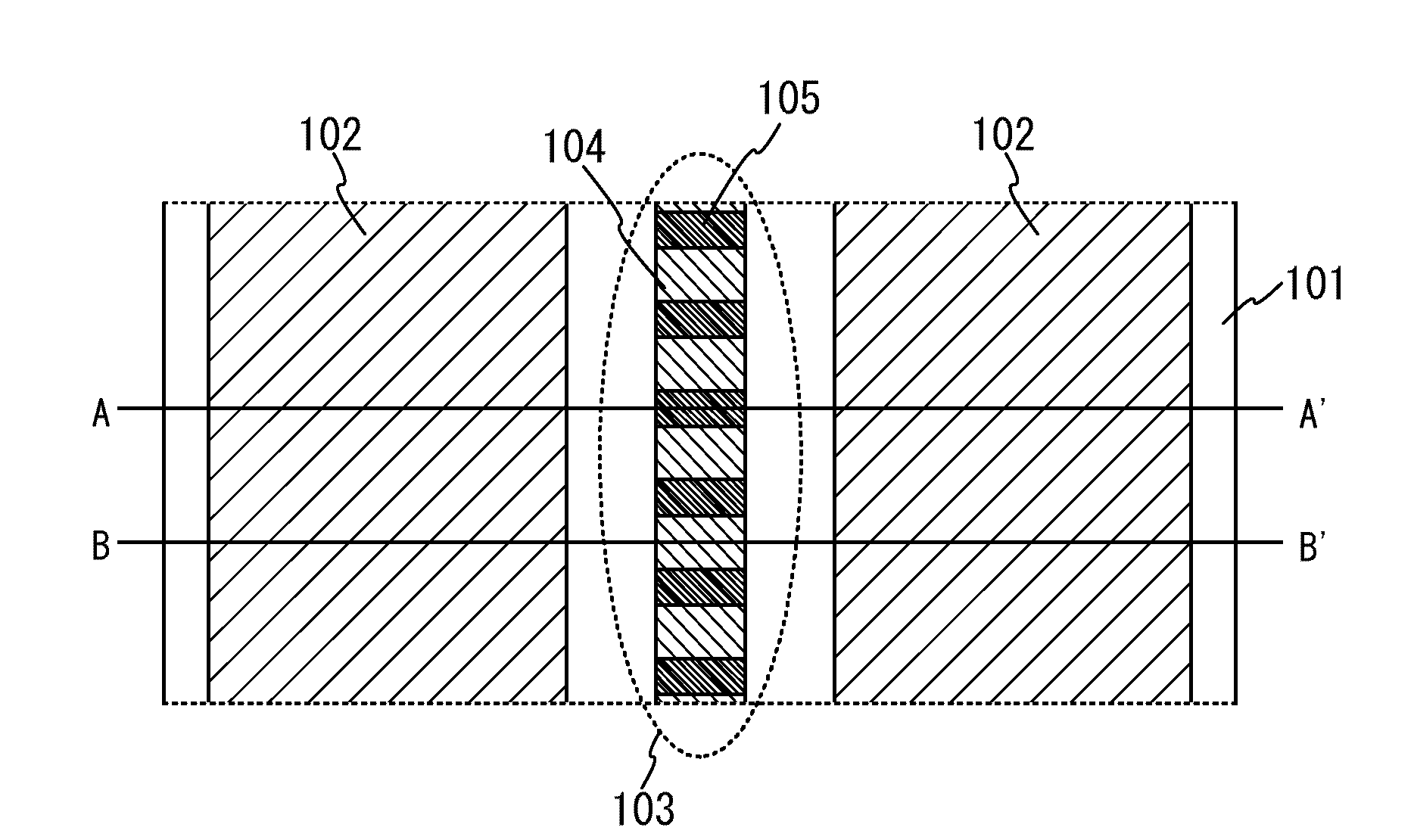
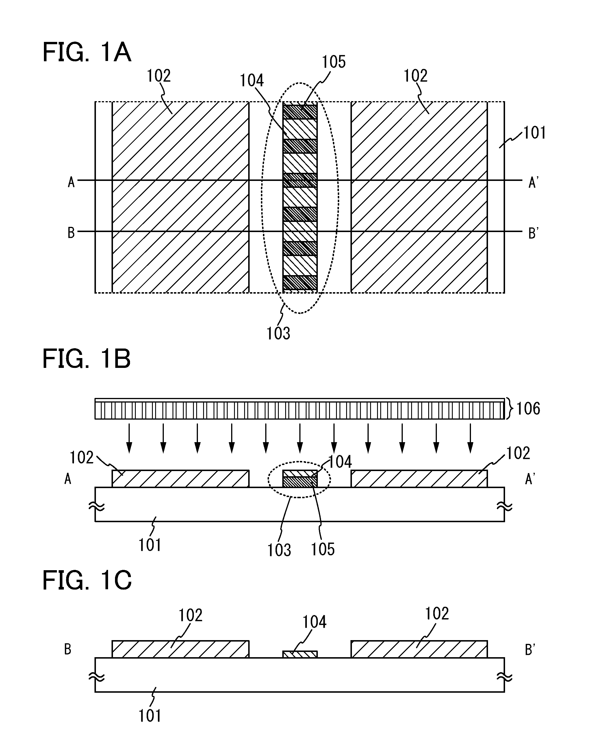
[0043]A solid-state dye laser which is an embodiment of the present invention is provided with first light-emitting bodies 102 and an optical resonator 103 over a substrate 101 having a property of not absorbing light such as a substrate having an insulating surface, as illustrated in the top view of FIG. 1A. The optical resonator 103 has a structure in which a second light-emitting body 104 is stacked over a grating (diffraction grating) 105 formed over the substrate. Note that for the substrate 101, glass, quartz, plastic, or the like can be used for example.
[0044]The grating 105 formed over the substrate can be formed using a light-transmitting material such as silicon oxide or silicon nitride by a known photolithography technique or nanoimprint technique.
[0045]FIG. 1B is a cross-sectional view taken along line A-A′ in FIG. 1A. Along line A-A′, the optic...
embodiment 2
[0063]In Embodiment 2, a structure of a solid-state dye laser, which is an embodiment of the present invention different from that of Embodiment 1, will be described. That is, in the case where the solid-state dye laser has a sealing structure in Embodiment 1 (see FIG. 2C), a light source is not provided inside the sealing structure. In Embodiment 2, a case of providing a light source inside the sealing structure will be described.
[0064]A solid-state dye laser in Embodiment 2 can emit a laser beam from an optical resonator 303 by irradiating first light-emitting bodies 302 and a second light-emitting body304 with light from a light source (hereinafter referred to as an internal light source) 306 which is provided in a space surrounded by substrates 301 and 309 and a sealant 314 as illustrated in FIG. 3A. Note that in the solid-state dye laser illustrated here, light from the light source 306 is first absorbed by the first light-emitting bodies 302, edge surfaces of the optical reson...
embodiment 3
[0110]In Embodiment 3, a case where the areas per first light-emitting body and second light-emitting body, which are separately formed over the substrate, are small and the number of first light-emitting bodies and second light-emitting bodies, which are separately formed, is large as compared to the cases described in Embodiments 1 and 2 will be described with reference to FIGS. 4A to 4D.
[0111]FIG. 4A illustrates a case where gratings 405 are aligned in plural lines over a substrate 401 having an insulating surface. Here, the gratings 405 are aligned in four lines; however, the present invention is not limited to this and the number of lines may be changed as appropriate. Note that glass, quartz, plastic, or the like can be used for the substrate 401, for example.
[0112]The gratings 405 formed over the substrate 401 can be formed using a light-transmitting material such as silicon oxide or silicon oxynitride by a known photolithography technique or nanoimprint technique.
[0113]Furth...
PUM
 Abstract
Description
Claims
Application Information
 - R&D
- Intellectual Property
- Life Sciences
- Materials
- Tech Scout
- Unparalleled Data Quality
- Higher Quality Content
- 60% Fewer Hallucinations
Browse by: Latest US Patents, China's latest patents, Technical Efficacy Thesaurus, Application Domain, Technology Topic, Popular Technical Reports.
© 2025 PatSnap. All rights reserved.Legal|Privacy policy|Modern Slavery Act Transparency Statement|Sitemap|About US| Contact US: help@patsnap.com


