
System And Method For Camera Imaging Data Channel

a camera imaging and data channel technology, applied in the field of system and method for camera imaging data channel, to achieve the effect of no extra data cos

Inactive Publication Date: 2010-01-28
LIU XU +2
View PDF4 Cites 266 Cited by
  • Summary
  • Abstract
  • Description
  • Claims
  • Application Information

AI Technical Summary

Benefits of technology

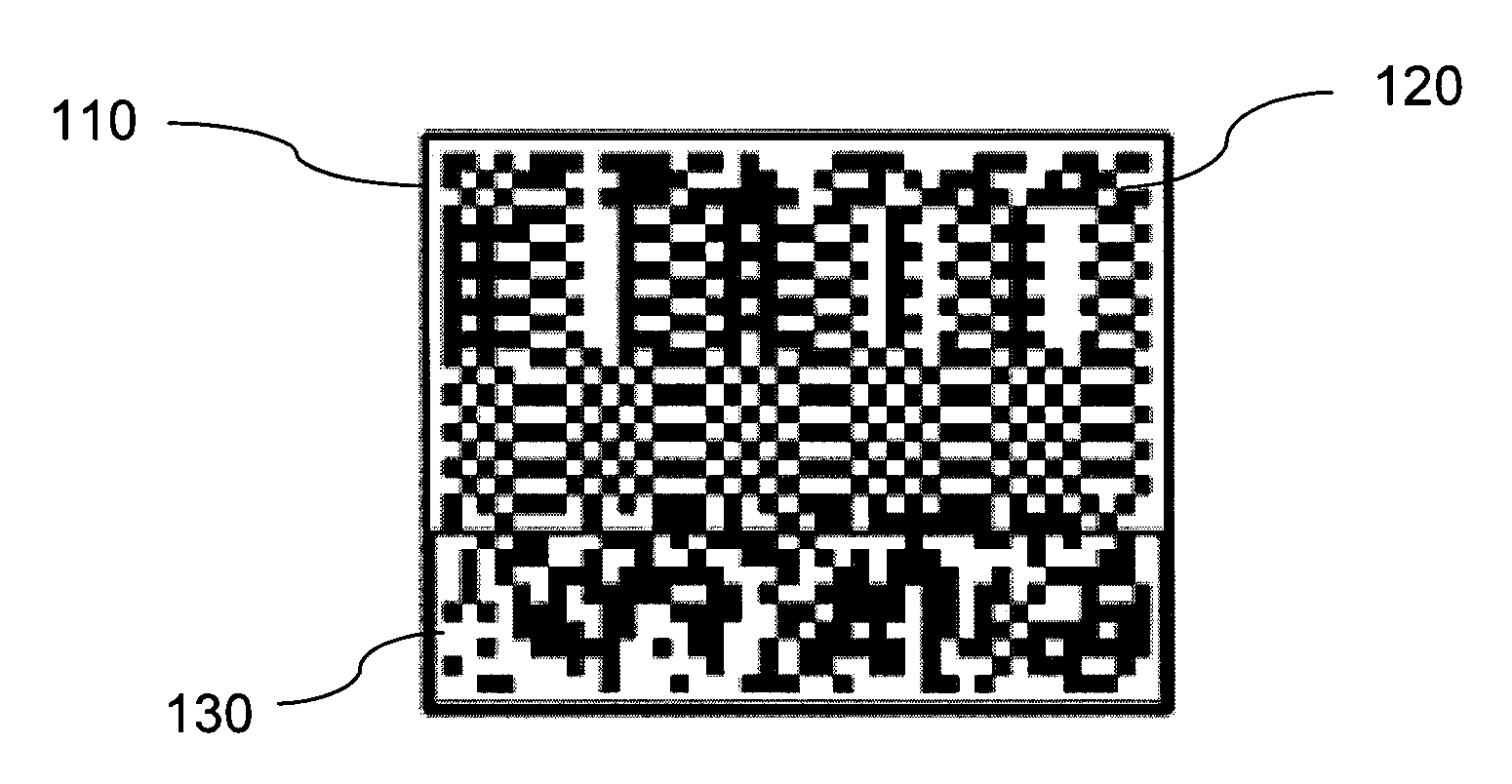
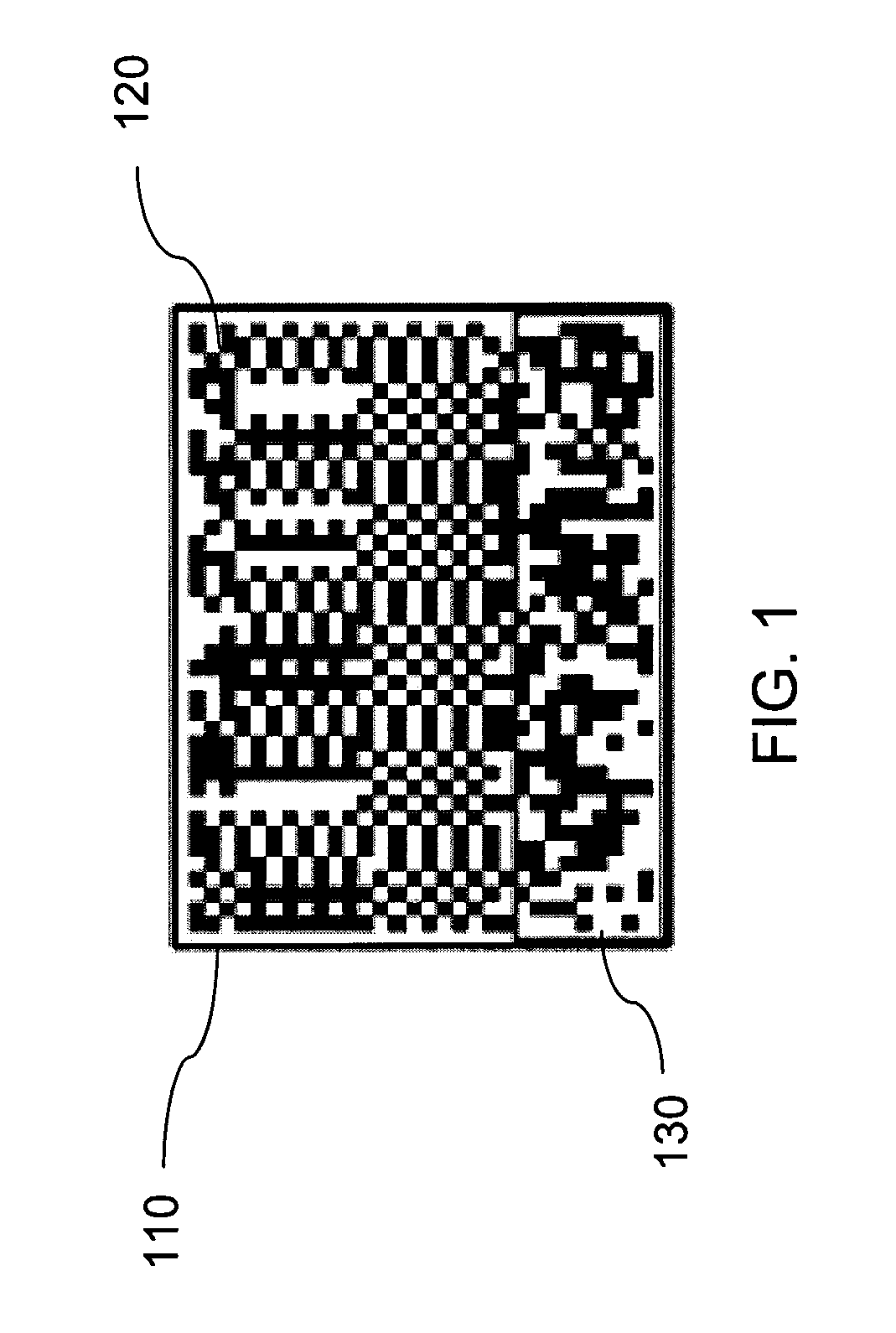
[0016]The present invention is a novel system and method which allows a camera to be repurposed to download data from an image or a series of images. This camera-based system has several unique advantages. First, it uses existing hardware infrastructure and local communication, so there is no extra data cost. Some of the existing data downloading methods, such as wireless communication data networks (GPRS / CDMA), will trigger charges by service providers. Second, the present invention can be implemented predominantly through software. Users do not need to connect their phones with PCs through cables or BlueTooth adaptors and there will be no complex driver installation or synchronization problems. Users need to simply aim the camera at the visual code, or “V-Code”.
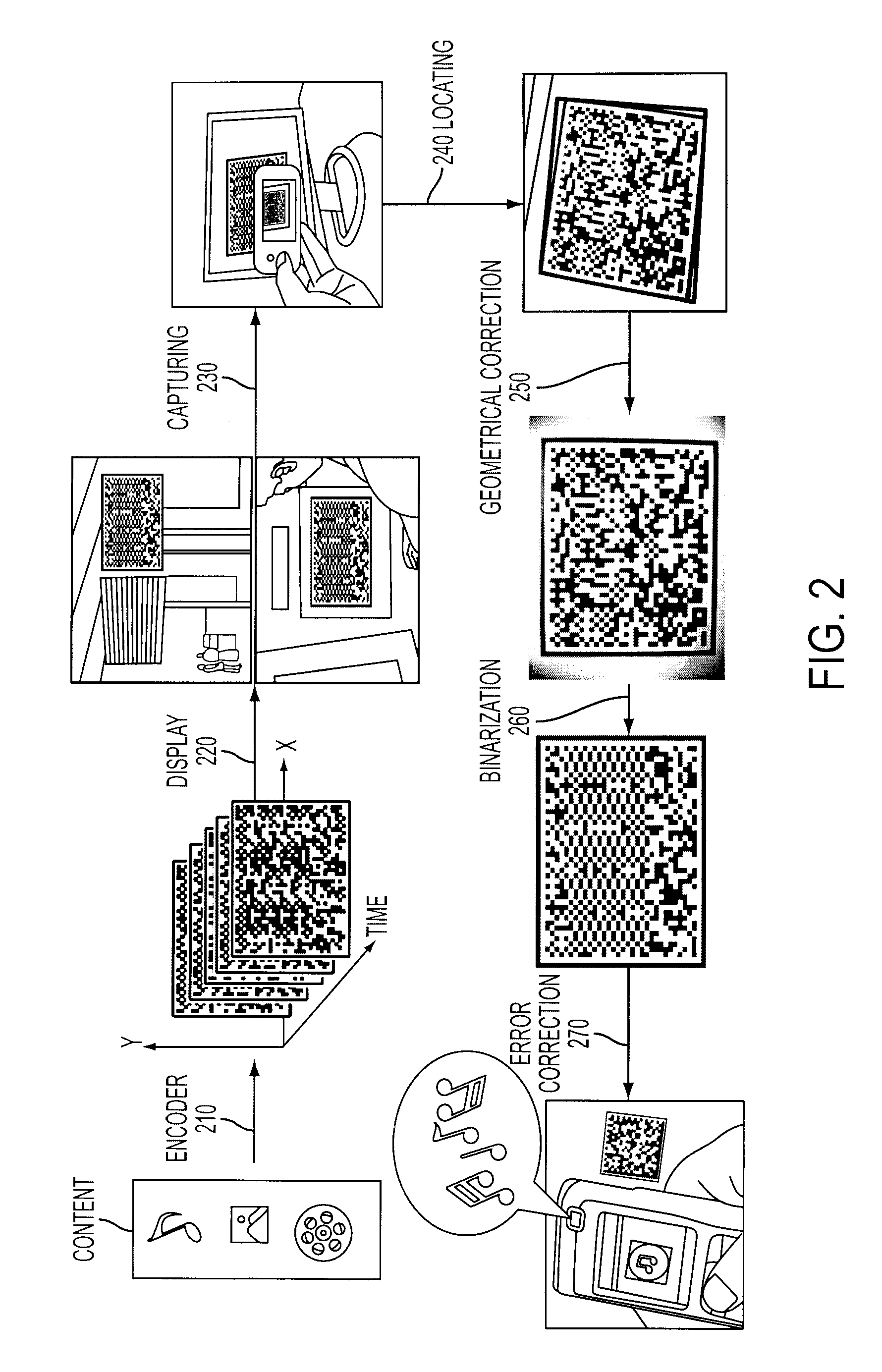
[0018]The decoding step may comprise fast perspective correction. Instead of solving a plane-to-plane projection which requires large amount of floating points operation. We use intermediate affine coordinate transform which simplifies homogeneous estimation to inverting two signs of a homography. In this way we eliminate floating operations and the speed of perspective correction is significantly improved. Further, colors may be embedded in the two-dimensional bar codes.

Problems solved by technology

1) Target Location: The first step is to locate the target's position. On traditional desktop / workstation environments, sophisticated methods can be applied. For mobile devices, however, detection often needs to run in real time and consume less resource to save power (which means the longer battery life). Lightweight or approximate features are explored to achieve these goals. For example, Viola and Jones used efficient rectangular features in “Robust real-time face detection,” Int. J. Comput. Vision, vol. 137-154 (2004), for face detection on a Compaq PDA. Road sign or text detection often uses heuristic methods. For 2D barcode acquisition an unique pattern is often used to identify by its location. For example, a Maxicode contains a bull eye pattern at its center, a QR Code uses three squares at its three corners as locator patterns, and Datamatrix has its two perpendicular edges. Algorithms are designed to locate these locator patterns efficiently.
2) Image Enhancement and Distortion Correction: Camera phones often use cheap CMOS sensors with fixed focus. Compared with digital cameras with high quality CCD sensors, images captured by camera phones are relatively low quality. One problem is uneven lighting. Images captured by camera phones often have cast or attached shadows. Adaptive binarization is often used to reduce the effect of shading and uneven lighting. Another problem is perspective distortion. When users capture images, it is impractical for them to hold devices at a perfectly right angle. As a result, perspective distortion is inevitable and geometrical correction is required to normalize the image before recognition. Focus is another problem to be tackled. Cameras in mobile phones are designed to take pictures of people and scenes. For this reason the focal length of camera is often set to a distance >1 foot. To keep a reasonable resolution, however, physical barcodes need to be put close enough to cameras, leading to blur in the acquired image. A super resolution method was proposed to solve this problem in S. Baker and T. Kanade, “Limits on superresolution and how to break them,” IEEE Trans. Pattern Anal. Mach. Intell., vol. 1167-1183, 2002, but the complexity of the algorithm prevents it from being run on mobile devices. To handle these problems the symbology should be robust enough to compensate for the adverse effects caused by image degradation.
3) Recognition: For recognition, features with geometric invariance are often selected since images are usually captured by cameras at arbitrary angles. Geometric invariants are used explicitly or implicitly in previous work. See I. Weiss, “Geometric invariants and object recognition,” Int. J. Comput. Vision, vol. 207-231, 1993 and F. Mindru, T. Tuytelaars, L. V. Gool, and T. Moons, “Moment invariants for recognition under changing viewpoint and illumination,” Comput. Vis. Image Underst., vol. Explicit features include moments or the Fourier descriptors. See S. K. W. Kwok and J. C. H. Poon, “Viewpoint-invariant Fourier descriptors for 3 dimensional planar shape representation,” Electronics Letters, vol. 1775-1776, 1996, 00135194. An example of implicit features is to locate feature points based on reference points, which is commonly used for decoding 2D barcodes. For example, when the three rectangular location patterns of a QR code are located, the positions of other unit cells in the QR code can be decided and the encoded information will be decoded.
One challenge for camera phone related applications is the user interface.
Due to the physical limitation of mobile phones (small keypads, small displays, etc.), the designing of interface to facilitate users' interaction with the device is an important problem.
1) Image Distortion: When users capture images, one cannot expect them keep the image plane of a camera phone parallel with the physical plane. Perspective distortion is expected.
2) Small input keypads and displays: The user interface should be intuitive enough.
Images captured by camera phones are often of low quality due to perspective distortion, noise and shading.
Decoding errors are inevitable, and extra bits need to be inserted to correct them.
However, decoding of convolved block codes requires computational power beyond current mobile devices.
Especially, the floating point Viterbi decoding inhibits real-time performance on today's camera phones.
While such systems and methods have proven useful, they fail to take advantage of the fact that cameras are increasingly being incorporated into such devices.

Method used


Image

  • System And Method For Camera Imaging Data Channel
  • System And Method For Camera Imaging Data Channel
  • System And Method For Camera Imaging Data Channel

Examples


Embodiment Construction

[0034]Embedding information in images (see Kutter, M., And Petitcolas, F. A., “Fair evaluation methods for image watermarking systems,”Journal of Electronic Imaging 9 (October 2000), 445-455) and videos (see Dittmann, J., Stabenau, M., and Steinmetz, R., “Robust mpeg video watermarking technologies,”MULTIMEDIA '98: Proceedings of the sixth ACM international conference on Multimedia, ACM Press, New York, N.Y., USA, 71-80 (1998)) has been studied for digital watermarking. The purpose of watermarking typically is for authorization and protection of the media. In the preferred embodiments of the present invention, data is encoded to facilitate the communication between the mobile device and the computer.

[0035]Known 2D barcode systems such as CyberCode (see Rekimoto, J., And Ayatsuka, Y., “Cybercode: designing augmented reality environments with visual tags,”DARE '00: Proceedings of DARE 2000 on Designing augmented reality environments, ACM Press, New York, N.Y., USA, 1-10 (2000)) and QR...


PUM


Abstract

A system and method for using cameras to download data to cell phones or other devices as an alternative to CDMA / GPRS, BlueTooth, Infrared or cable connections. The data is encoded as a sequence of images such as 2D bar codes, which can be displayed in any flat panel display, acquired by a camera, and decoded by software embedded in the device. The decoded data is written to a file. The system and method meet the following challenges: (1) To encode arbitrary data as a sequence of images. (2) To process captured images under various lighting variations and perspective distortions while maintaining real time performance. (3) To decode the processed images robustly even when partial data is lost.

Description

CROSS-REFERENCE TO RELATED APPLICATIONS[0001]The present invention claims the benefit of the filing date of U.S. Provisional Patent Application Ser. No. 60 / 865,602 filed on Nov. 13, 2006 by Xu Liu, David Doermann and Huiping Li. This prior application is hereby incorporated by reference in its entirety.STATEMENT REGARDING FEDERALLY SPONSORED RESEARCH OR DEVELOPMENT[0002]Not applicable.BACKGROUND OF THE INVENTION[0003]1. Field of the Invention[0004]The present invention relates to a system and method for using cameras, such as in a cell phone, to download data.[0005]2. Brief Description of the Related Art[0006]Previously, work has been performed on mobile vision and recognition, mobile interaction and error correction coding.[0007]The combined image acquiring, processing, storage and communication capability in mobile phones rekindles researchers' interests in applying traditional pattern recognition and computer vision algorithms on camera phones in the pursuit of new mobile applica...

Claims


Application Information

Patent Timeline
IPC IPC(8): G06K7/10H03M13/07H04L9/00G06F11/10G09C5/00
CPCG06K7/1093H03M13/1515G06K7/1095
Inventor LIU, XUDOERMANN, DAVIDLI, HUIPING
Owner LIU XU
Learn More