Carbon Nanostructure Electrode Based Sensors: Devices, Processes and Uses Thereof
- Summary
- Abstract
- Description
- Claims
- Application Information
AI Technical Summary
Benefits of technology
Problems solved by technology
Method used
Image
Examples
example # 1
Example #1
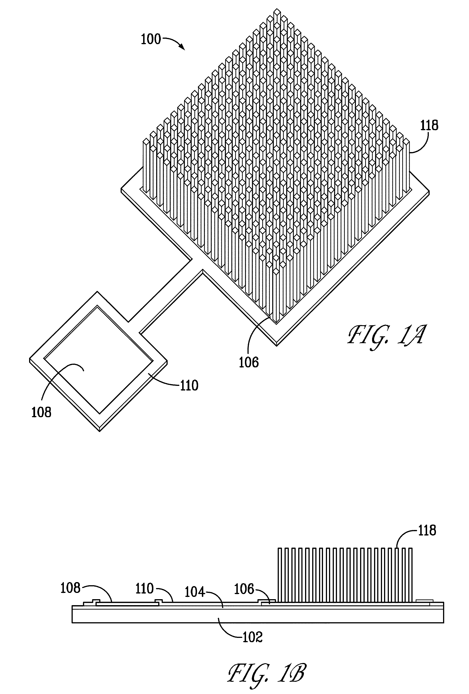
[0441]CHLORINE DETECTION. Free Chlorine [HClO] and Total Chlorine [HClO & RHNCl & Cl-RH] may be detected with the Device in FIG. (1) when the CNTs are configured as a Working Electrode in an electrolytic cell configuration. By the application of the appropriate votage bias of 1.1V vs. Ag / AgCl (Ref.) free Chlorine (or HClO) will directly reduce in water according to the following reactions:
A. Free Chlorine Measurement with No Dopant Requirement:[0442]Cl2(g)+H2O═HClO+HCl [pK(a1)=3.5][0443]HClO═H+ClO−[pK(a2)=7.5][0444]HClO+2e−+H2O═HCl+H2O2
[0445]The CNT islands in FIG. (3) are defined Working electrodes patterned from the Ni catalyst surface film. E-beam lithography can define the Ni film patterns with a resolution of 20-100 nm. Within this pad dimension, several CNTs will grow to form the working electrode. The ensemble of these 100 nm CNT islands make up the total working electrode surface. As depicted by the above electrochemical reaction, HClO will reduce to HCl and other ...
example # 2
Example #2
[0455]CALCIUM ION DETECTION: Charge Coupled Devices:
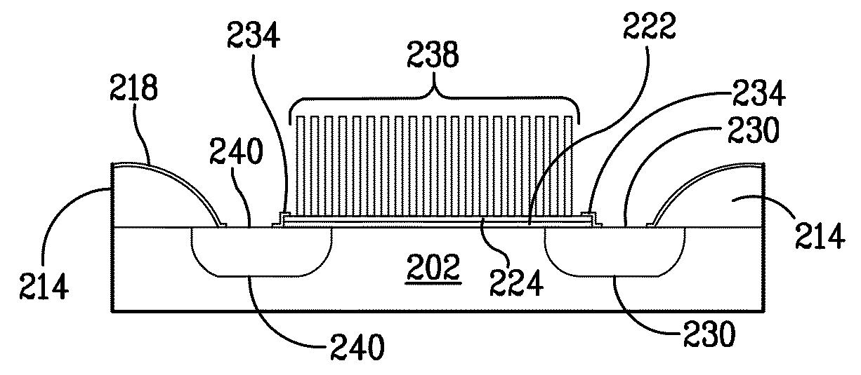
[0456]The passive device of FIG. (1) may be applied as an ion selective ion sensor by doping the CNT array with ionophore or ion exchange ligands. Such a sensor responds to the test sample ion content according to the equation:
E=Eo+S ln [ai+KijΣaij−Eref]
where; Eo is the standard potential (ln ai intercept)
[0457](S ln ai−Eref) is the chemical potential term for the ion i.
[0458]Kij Σaij is the interference error term for ion j.
[0459]The assumptions are; E is referenced to Eref, slope is 50 mV for n=1, ionic strength is constant or activity coefficients χ=1, and Kij=>0. Hence, the CNT E response is a Log function of the target ion concentration (or ai).
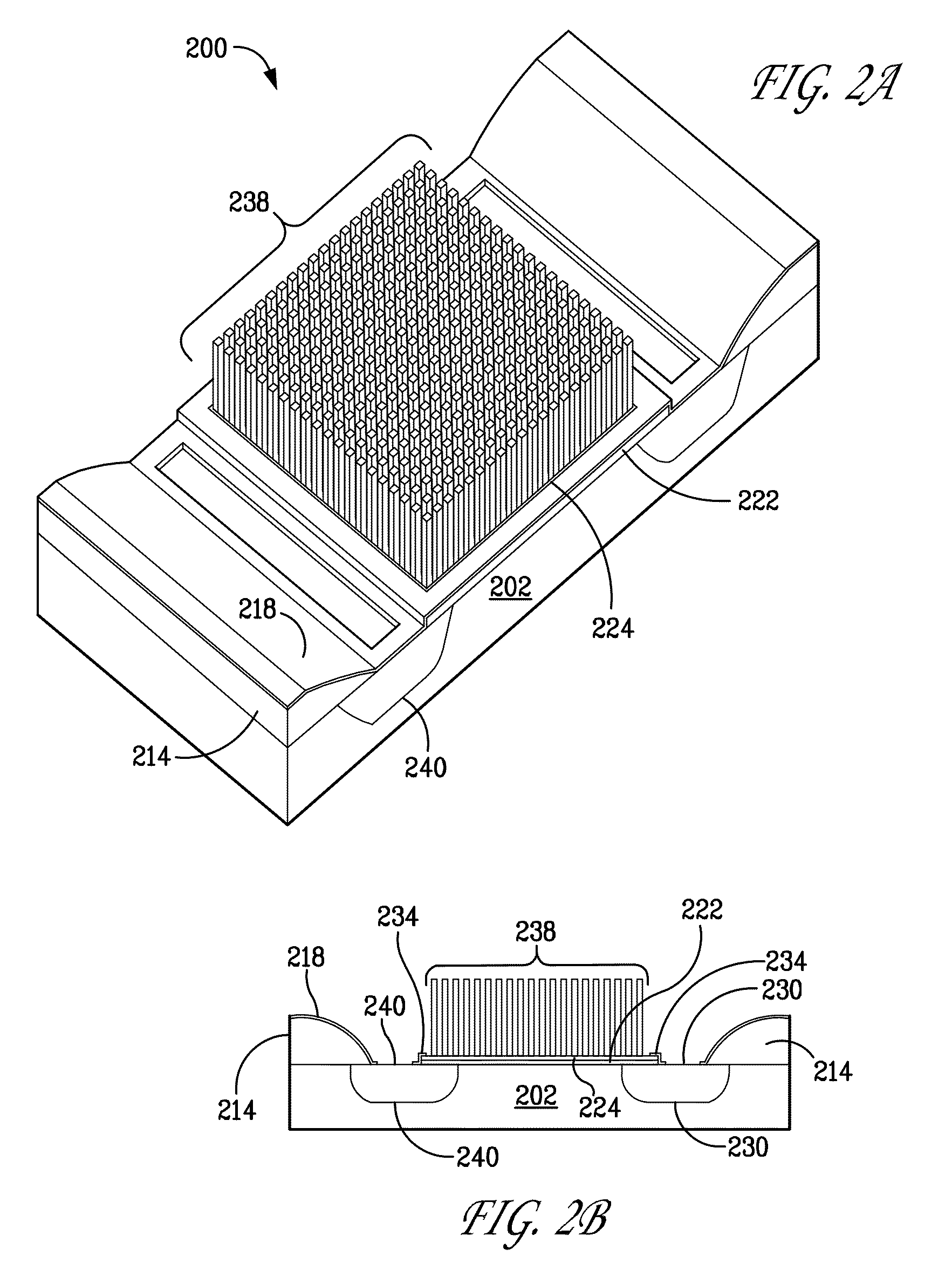
[0460]The doping of the CNT with ionophore may assume the “peapod” structure with ionophore occupying the CNT interior void space. Alternatively, doping may be achieved by dielectric polymers coating (cladding) the CNT and impregnating the polymer with ionophore (See FIG. [10]...
example # 3
Example #3
[0479]AMMONIA & CARBON DIOXIDE DETECTION / The sensor of FIG. (10) is based on the cladded peapod structure of FIG. (7). It couples the ammonium ion specific CNT peapod with a gas barrier polymer cladding. PTFE cladding is an effective NH3 gas separator from dissolved NH4+OH− (ammonia) in solution. Nonactin is a selective ionophore for NH4+ that is immobilized within the peapod. NH3 permeates through the cladding and NH4+ is captured and bound by the nonactin to generate CNT charge.
[0480]Similarly, CO2 can permeate gas barrier (cladding) to bind with Heptyl 4-trifluoroacetylbenzoate as carbonate anion. Alternatively, CO2 can be detected as a pH change with Tridodecylamine. Both mechanisms separate the gas from solution and generate ionic charge on the CNT. The measurement is accomplished by electrometric EMF measurement of a passive CNT array sensor or by active CNT-gated FET device. In either case the chemical potential of the NH4+ or CO3= is in equilibrium with the EMF of ...
PUM
 Abstract
Description
Claims
Application Information
 - R&D
- Intellectual Property
- Life Sciences
- Materials
- Tech Scout
- Unparalleled Data Quality
- Higher Quality Content
- 60% Fewer Hallucinations
Browse by: Latest US Patents, China's latest patents, Technical Efficacy Thesaurus, Application Domain, Technology Topic, Popular Technical Reports.
© 2025 PatSnap. All rights reserved.Legal|Privacy policy|Modern Slavery Act Transparency Statement|Sitemap|About US| Contact US: help@patsnap.com


