
Implant surfaces and treatments for wear reduction

a technology for implants and surfaces, applied in the field of surface treatment, can solve problems such as the acceleration of the degradation of the implant surface, and achieve the effects of enhancing the relative amount of one or more components and enhancing the chromium-to-cobalt ratio

Inactive Publication Date: 2009-10-29
DEPUY PROD INC
View PDF0 Cites 12 Cited by
  • Summary
  • Abstract
  • Description
  • Claims
  • Application Information

AI Technical Summary

Benefits of technology

[0006]The implant surface can be contacted with an acid during surface treatment, consistent with various embodiments. In some embodiments, the acid is contacted with the implant surface after the oxide-containing layer is formed. The latter can aid in selectively enhancing a relative amount of one or more components in the oxide-containing layer, though other techniques can also be potentially utilized. For example, the acid can be used to treat an oxide-containing layer, resulting in an enhanced chromium-to-cobalt ratio (e.g., greater than about 2) by selectively removing cobalt oxide relative to chromium oxide. In some embodiments, an implant surface can be smoothed before the oxide-containing layer, which can be thick, is formed thereon, and optionally after the pits are formed on the surface. The smoothing can be carried out by any number of processes such as polishing. The smoothing can result in at least a portion of the implant surface having a smoothness characterized by a Ra value less than some designated value such as about 1 μm, about 0.6 μm, or 0.1 μm.

Problems solved by technology

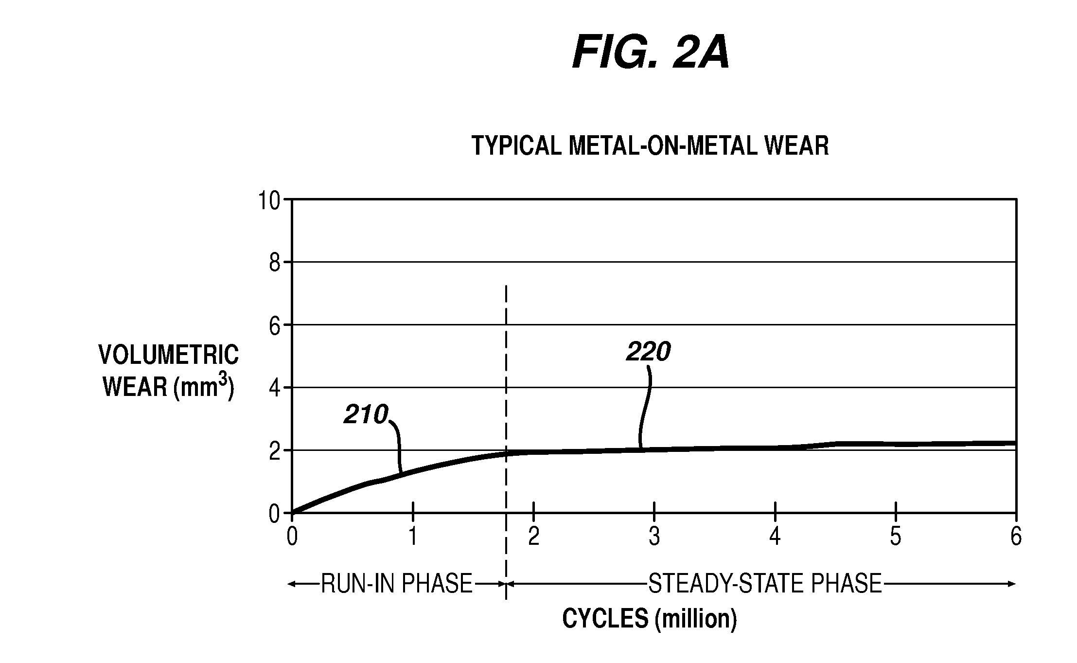
Such particles can grind and degrade a MOM surface, leading to increased friction between joint surfaces that further accelerates degradation of the implant surface.

Method used


Image

  • Implant surfaces and treatments for wear reduction
  • Implant surfaces and treatments for wear reduction
  • Implant surfaces and treatments for wear reduction

Examples


example 1

Treated CoCrMo Disk Surface with Chemical Etching

[0066]FIGS. 4A-4C depict data associated with a treated cobalt-chromium-molybdenum disk. FIG. 4A shows a scanning electron micrograph (SEM) of a cobalt-chromium-molybdenum disk after chemical etching in 100 mLs of 6 N HCl for 8 hours at 60° C. FIG. 4B shows the surface of the disk of FIG. 4A after the surface was polished with 0.1 μm alumina to an Ra value of about 0.1 μm, treated for about 1 hour with a plasma formed from molecular oxygen using a 1000 watt energy source, and subsequently exposed to a 6M HCl treatment for about an hour. FIG. 4C depicts a graph of the results of a XPS depth scan performed on the treated substrate of FIG. 4B. The traces 410, 420, 430 correspond with the atomic percentages as a function of depth of chromium, cobalt, and molybdenum, respectively. Accordingly, the graph of FIG. 4C shows that the chromium to cobalt ratio at the surface is about 13, and the oxide-containing layer of the surface is a little o...

example 2

Treated CoCrMo Disk Surface with Electrochemical Etching

[0067]FIGS. 5A-5F depict data associated with another treated cobalt-chromium-molybdenum disk. FIG. 5A shows a SEM of a cobalt-chromium-molybdenum disk after electrochemical etching in 300 mLs of 1 N HCl for 5 minutes at room temperature. The disk served as the anode and a Pt electrode was used as a cathode. A current density of 32 mA / cm2 was utilized. FIG. 5B shows a section of the same surface as FIG. 5A but magnified about 5 times. The SEMs indicate that lower acid concentrations, lower temperatures, and shorter etching times, can be used effectively in electrochemical etching relative to the chemical etching of Example 1.

[0068]FIG. 5C shows the surface of FIG. 5A after the disk was mechanically polished with 0.1 μm alumina to a Ra value of about 0.1 μm. FIG. 5D shows a magnified view of a section of the surface depicted in FIG. 5C.

[0069]FIG. 5F shows the surface of the disk of FIG. 5C after the surface was treated for about...

example 3

Treated Femur Head

[0070]FIGS. 6A and 6B depict the treated surface of a chromium-cobalt-molybdenum femur head prosthesis. FIG. 6A shows a 500OX magnification SEM of an electrochemically etched femur head. FIG. 6B shows a 5000× magnification SEM of the same femur head after the surface was polished with ⅗μm cloth to a Ra value of about 0.1 μm, treated with an oxygen plasma formed with a 1000 watt energy source for about one hour, and treated with nitric acid at 54° C. for about half an hour. FIG. 6B shows that the polishing results in a substantially smoother surface. FIG. 6C presents a plot f the results of a XPS depth scan performed on the treated femur head of FIG. 6B. The traces 610, 620, 630 correspond to the atomic percentages as a function of depth for cobalt, chromium, and molybdenum, respectively. The traces show that at the surface of the head, the chromium to cobalt ratio is a little over about 3.5.


PUM

PropertyMeasurementUnit
Lengthaaaaaaaaaa
Sizeaaaaaaaaaa
Surface roughnessaaaaaaaaaa

Abstract

Methods and devices directed to surface treatment of implants are disclosed. In some instances, the surfaces are treated to have one or more characteristics that can impart low wear properties when the implant is utilized in a subject. As one example, a metallic surface of an implant can be treated to form pits in the surface, followed optionally by a smoothing step to reduce the roughness of the pitted surface. A plasma treatment can be used to form an oxide-containing layer (e.g., highly corrosion resistant and / or thick) on the surface. An acid treatment can also be used as part of a process for forming an oxide-containing layer. Other examples of method are also disclosed, along with characteristics of implant surfaces that can exhibit low wear properties.

Description

FIELD OF THE APPLICATION[0001]The technical field of the present application is directed to treatment of surfaces, and in some instances to the surfaces of implants to help reduce wear thereon.BACKGROUND[0002]Implants for use as replacement structures in subjects have become widespread in their application. Improving the durability and longevity of such implants has numerous advantages such as extending the lifetime of such implants, and reducing the need for future replacement of such implants.[0003]FIGS. 1A and 1B depict a portion of a head-cup joint implant 100. The head 110 and the cup 120 of the implant can move relative to one another as a ball in socket joint. In instances where the head 110 and cup 120 are each metallic, the opposite surfaces 115, 125 of the structures 110, 120, which can be complementary in shape, can be termed metal-on-metal (herein “MOM”) surfaces, which form an interface 130 between the structures 110, 120. As depicted in FIGS. 1A and 1B, a MOM surface d...

Claims


Application Information

Patent Timeline
IPC IPC(8): B44C1/22
CPCA61L27/04A61L27/30C25F3/02A61L2400/18A61L27/50
Inventor YANG, SOPHIE XIAOFANSALVATI, JR., LAWRENCE
Owner DEPUY PROD INC
Learn More