Non-aqueous electrolyte and non-aqueous electrolyte secondary battery using the same

Active Publication Date: 2009-10-08
NEC ENERGY DEVICES LTD
View PDF3 Cites 14 Cited by
  • Summary
  • Abstract
  • Description
  • Claims
  • Application Information

AI Technical Summary

Benefits of technology

[0018]In view of the above-identified circumstances, it is therefore the object of the present invention to provide a non-aqueous electrolyte that can suppress decomposition of a solvent, improve the cycle life of a secondary battery, suppress the increase of resistance of a secondary battery and improve the capacity retention ratio of a secondary battery, and a non-aqueous electrolyte secondary battery using the same.
[0028]An electrolyte to be used for a secondary battery according to the present invention contains a disulfonic acid ester expressed by the above chemical formula 1. A compound expressed by the above chemical formula 1 contributes to forming a passive film on the interface of one of the electrodes of a battery so as to consequently suppress decomposition of solvent molecules. In the case where the positive electrode of a battery is made of an oxide that contains manganese, such a compound suppresses elution of manganese and prevents eluted manganese from adhering to the negative electrode of the battery. Therefore, it is possible to improve the cycle performances of a secondary battery and suppress the rise of resistance thereof due to the effect of forming a film on the negative electrode and alleviating the adverse effect of eluted manganese by using an electrolyte according to the present invention in the secondary battery.
[0029]Thus, according to the present invention, it is possible to suppress decomposition of solvent of the electrolyte of a non-aqueous electrolyte secondary battery by using an electrolyte containing an aprotic organic solvent and a compound expressed by the chemical formula 1. Additionally, according to the present invention, it is possible to improve the charge-discharge efficiency and the cycle life of a non-aqueous electrolyte secondary battery. Still additionally, according to the present invention, it is possible to suppress the rise of resistance of a secondary battery. Furthermore, according to the present invention, it is possible to improve the capacity maintenance ratio of a secondary battery. An electrolyte to be used for a secondary battery according to the present invention can be manufactured stably in a simple manner by way of a step of dissolving a compound expressed by the above chemical formula 1 in a solvent and a step of dissolving a lithium salt in the solvent.

Problems solved by technology

However, such a lithium fluoride film is produced as a result of reaction of the electrode interface and a solution and hence one or more than one side reaction products are apt to be mingled in the surface film to make it difficult to obtain a homogeneous film.
In such occasions, no homogeneous thin film can be formed and water or hydrogen fluoride and lithium may react with each other to give rise to problems.
If the reaction is insufficient, unnecessary compounds are left in addition to the fluorides to consequently reduce the ion conductivity.
Furthermore, the scope of fluorides and that of electrolytes that can be utilized are limited and it is difficult to form a stable surface film at a high yield rate with such a technique of forming a fluoride layer by means of a chemical reaction on the interface.
However, the reaction can be easily become uneven to make it difficult to form a homogeneous lithium fluoride film when a surface film exists in advance on the surface of the lithium metal and particularly when a plurality of different compounds exists there.
Therefore, it is difficult to obtain a lithium secondary battery having sufficient cycle characteristics.
However, with the technique of JP-A-11-288706 that uses a flat rolled lithium metal sheet, the lithium sheet is apt to be exposed to the atmosphere and a film attributable to moisture is likely to be formed on the surface to make active sites exist inhomogeneously so that it is difficult to produce an intended stable surface film and a satisfactory effect of suppressing generation of dendrite cannot be achieved.
However, this method is not satisfactory although it provides an effect of improving the cycle life to a certain extent.
Additionally, the use of a lithium imide salt such as LiN(C2F5SO2)2 that is relatively expensive as electrolyte is indispensable and the cycle characteristics are not improved if a complex of some other lithium salt (such as popular LiPF6) transition metal and CF3SO3− ions is added because a complex of transition metal and imide anions is not produced.
Furthermore, there arises a problem of high internal resistance of battery because resistance of electrolyte increases if compared with the use of LiPF6 when lithium imide salt is employed as the electrolyte.
However, the capacity of a battery using such a negative electrode can fall rapidly when the operation cycle is repeated because aluminum reacts with a small quantity of water.
However, cracks that appear in the solid electrolyte due to the change in the stress occurring at the time of inclusion of lithium ions and also at the time of elimination of lithium ions induce degradation of the characteristics.
Additionally, reactions do not take place uniformly on the surface of the negative electrode because of the inhomogeneity of the solid electrolyte due to crystal defects and other causes to consequently reduce the cycle life.
However, this technique does not provide a satisfactory film effect and is accompanied by a problem that an electric charge attributable to decomposition of solvent molecules or anions appear as irreversible capacity component to induce a fall of the initial charge-discharge efficiency.
However, the prior art does not provide a satisfactory film effect for improving the battery characteristics and still has the problems as listed below.
However, no technique has been known to date for controlling the film for an extended period of time.
However, the surface film is degraded and gradually loses its function of protective film as the battery is operated repeatedly.
It is believed that this problem arises because the layer of lithium or lithium alloy changes its volume as lithium is occluded and discharged, whereas the film of a lithium halide or the like on the layer hardly changes its volume so that internal stress arises in these layers and the interface thereof.
As such internal stress arises, particularly the surface film of a lithium halide is partly damaged to lower the effect of suppressing dendrite.
As for carbon materials such as graphite, the use of such a material does not provide a satisfactory film effect and gives rise to a problem that an electric charge attributable to decomposition of solvent molecules or anions appear as irreversible capacity component to induce a fall of the initial charge-discharge efficiency.
Furthermore, the minute amount of moisture existing in the negative electrode of graphite or amorphous carbon accelerates decomposition of the solvent of the electrolyte.
However, no technique has been known to date for controlling the film for an extended period of time.

Method used


Image

  • Non-aqueous electrolyte and non-aqueous electrolyte secondary battery using the same
  • Non-aqueous electrolyte and non-aqueous electrolyte secondary battery using the same
  • Non-aqueous electrolyte and non-aqueous electrolyte secondary battery using the same

Examples


example 1

Preparation of Battery

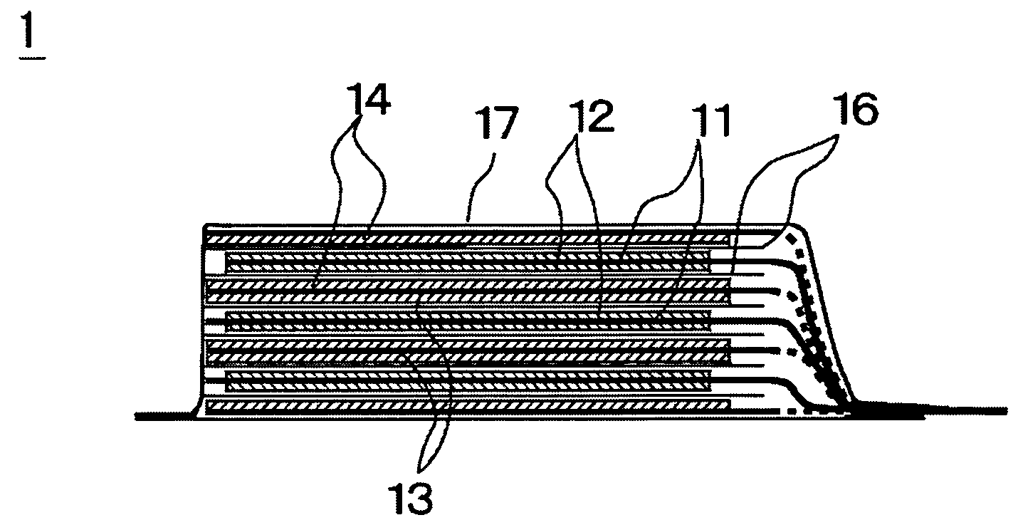
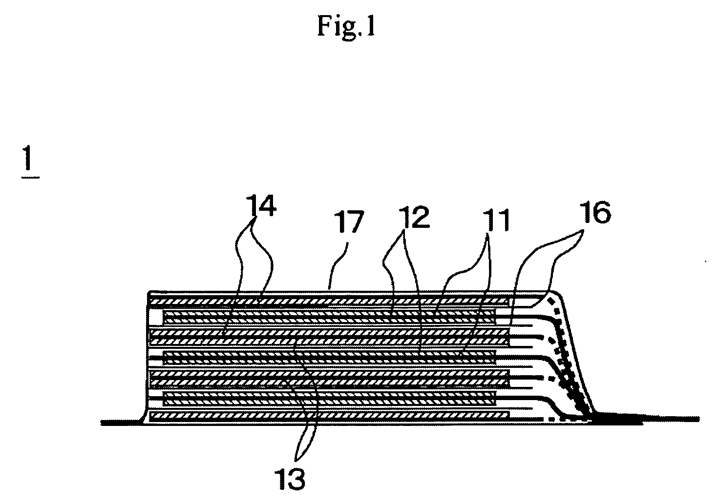
[0071]Now, the preparation of the battery of this example will be described below. A 20 micrometer-thick aluminum foil was used as positive electrode collector and LiMn2O4 was employed as positive electrode active substance. On the other hand, a 10 micrometer-thick copper foil was used as negative electrode collector and the negative electrode was prepared by depositing lithium metal as negative electrode active substance to a thickness of 20 micrometer on the copper foil by evaporation. A mixture solvent of EC and DEC (volume ratio: 30 / 70) was employed as solvent of electrolyte and LiN(C2F5SO2)2, which is a fluorine-containing organic lithium salt, was dissolved in the mixture solvent as supporting electrolyte by 1 mol / L. Additionally, compound 1 listed in Table 1 shown above was added to the electrolyte so as to be contained by 1 wt %. Then, the negative electrode and the positive electrode were laid one on the other with a polyethylene separator interposed b...

examples 2 , 3 and 4

EXAMPLES 2, 3 AND 4

[0073]Non-aqueous electrolyte secondary batteries were prepared in these examples as in Example 1 except that the compound number 1 was replaced by the respective compounds listed in Table 2 that is, by the compounds of the compound numbers 5, 7, 14 listed in Table 1 and the battery characteristics of these batteries were tested as in Example 1. Table 2 shows the results.

example 5

[0077]A secondary battery was prepared in this example as in Example 1 except that LiN(C2F5SO2)2 was replaced by LiPF6 as supporting electrolyte and the negative electrode was formed by mixing graphite powder, polyvinylidene fluoride dissolved in N-methyl-2-pyrolidone so as to operate as binder and a conductivity providing material into paste, applying the mixture paste to a copper foil and drying it.

[0078]The charge-discharge cycle test of this example was conducted at temperature of 20 degrees C. with a charge rate of 1 C, a discharge rate of 1 C, an end of charge voltage of 4.2V and an end of discharge voltage of 3.0V. The capacity maintenance ratio (%) is the value obtained by dividing the discharge capacity (mAh) after 400 cycles by the discharge capacity (mAh) at the 10th cycle. Table 3 below shows the results obtained from the cycle test.


PUM


Abstract

A non-aqueous electrolyte can suppress decomposition of a solvent, improve the cycle life of a secondary battery, suppress the rise of resistance of a secondary battery and improve the capacity maintenance ratio of a secondary battery A non-aqueous electrolyte secondary battery formed by using such a non-aqueous electrolyte includes a non-aqueous electrolyte containing an aprotic solvent and a disulfonic acid ester as expressed by chemical formula 1 shown below, a positive electrode and a negative electrode:

Description

CROSS-REFERENCE TO RELATED APPLICATIONS[0001]This application is based upon and claims the benefit of priority from prior Japanese Patent Application No. 2008-99224, filed Apr. 7, 2008, the entire contents of which are incorporated herein by reference.BACKGROUND OF THE INVENTION[0002]This invention relates to a non-aqueous electrolyte to be used for secondary batteries and also to a non-aqueous electrolyte secondary battery using the same.[0003]Non-aqueous electrolyte lithium ions and lithium secondary batteries formed by using a carbon material, an oxide, a lithium alloy or lithium metal for the negative electrode have been attracting attention as power sources for portable telephone sets, notebook type personal computers and so on because they can realize a high energy density. It is known that a film referred to as surface film, protective film or solid electrolyte interface (SEI) or simply as film (to be referred to as “surface film” hereinafter) tends to be formed on the surfac...

Claims


Application Information

Patent Timeline
IPC IPC(8): H01M10/40H01M4/587H01M10/052H01M10/0525H01M10/0567H01M10/0568H01M10/0569
CPCH01M10/052H01M10/0567Y02E60/122H01M10/0569H01M10/0568Y02E60/10
Inventor ISHIKAWA, HITOSHIKONO, YASUTAKAUTSUGI, KOJIHASHIZUME, YOKOKANEKO, SHINAKOKOBAYASHI, HIROSHI
Owner NEC ENERGY DEVICES LTD
Why Eureka
Try Eureka