Eureka AIR delivers breakthrough ideas for toughest innovation challenges, trusted by R&D personnel around the world.

Sulfonium salt-containing polymer, resist composition, and patterning process

a technology of sulfonium salt and polymer, applied in the direction of photosensitive materials, instruments, photomechanical equipment, etc., can solve the problems of insufficient acid strength, failure of resolution, and several lags in the development of the material, and achieve high acidity, facilitate efficient scission of acid labile groups, and high resolution

Active Publication Date: 2009-09-17
SHIN ETSU CHEM IND CO LTD
View PDF19 Cites 70 Cited by
  • Summary
  • Abstract
  • Description
  • Claims
  • Application Information

AI Technical Summary

Benefits of technology

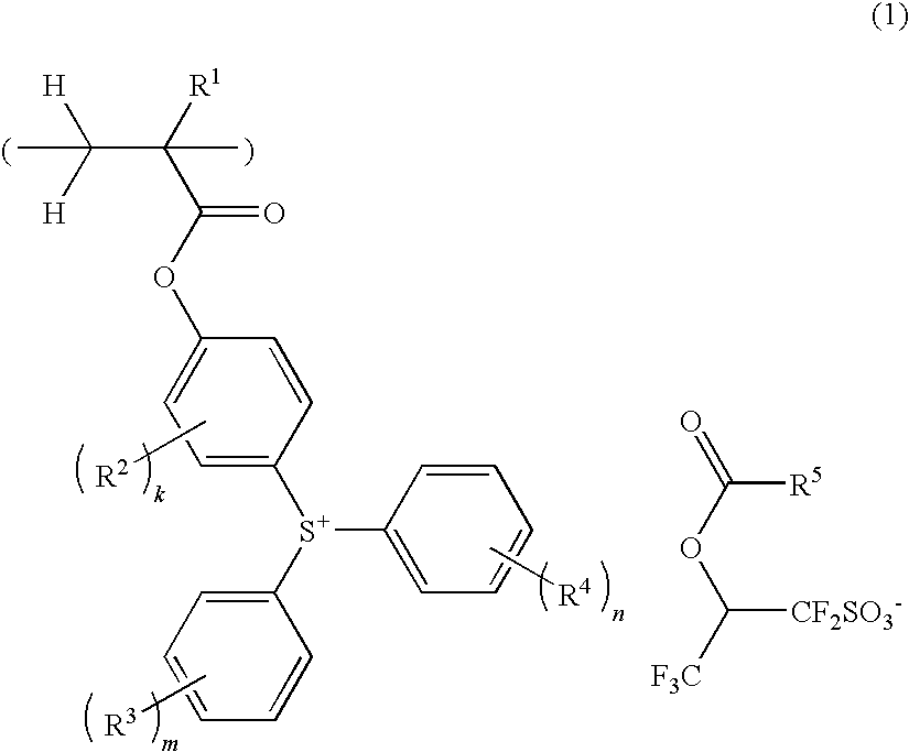
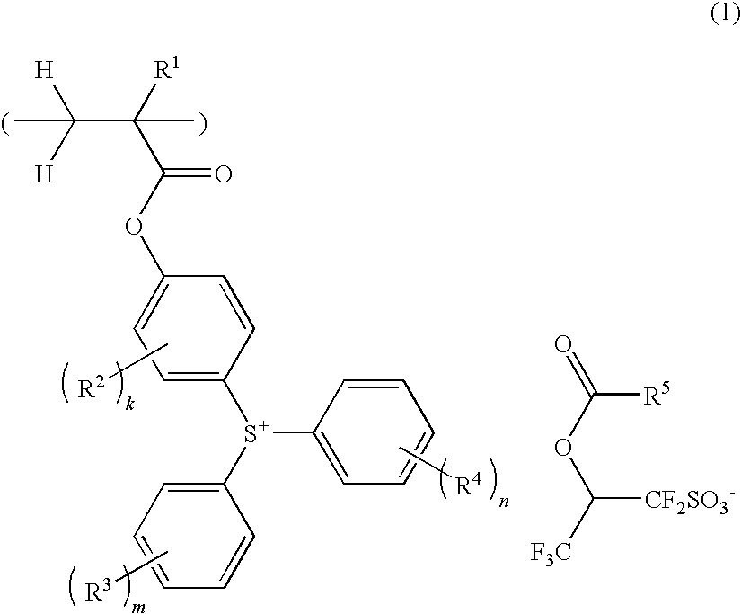
[0023]Making investigations on the assumption that a polymer in which a sulfonium salt capable of functioning as an acid generating unit is bonded at its cation side to the main chain can be improved in resolution and LER by optimizing the structure of the counter anion, the inventors have found that a polymer comprising recurring units of a sulfonium salt capable of generating sulfonic acid in response to high-energy radiation, heat or the like as represented by the general formula (1) can be used as a base resin to formulate a resist composition, which is improved in resolution and LER and best suited for precise micropatterning.
[0038]The resist composition of the invention allows the feature size of the pattern after development to be reduced by various shrinkage techniques. For example, the hole size can be shrunk by such known techniques as thermal flow, RELACS, SAFIRE, and WASOOM. More effective shrinkage of hole size by thermal flow is possible particularly when the inventive polymer is blended with a hydrogenated cycloolefin ring-opening metathesis polymer (ROMP) having a low Tg.Advantageous Effects of Invention

Problems solved by technology

Although lithography using F2 laser (157 nm) was initially thought promising as the next lithography for 45-nm node devices, its development was retarded by several problems.
However, the use of these photoacid generators in chemically amplified resist compositions for ArF lithography results in an insufficient acid strength to scissor acid labile groups on the resin, a failure of resolution, or a low sensitivity.
Thus these photoacid generators are not suited for the fabrication of microelectronic devices.
Among these, perfluorooctanesulfonic acid and homologues thereof (collectively referred to as PFOS) are considered problematic with respect to their non-degradability and biological concentration in the environment.
It is pointed out that with a progress of miniaturization, the edge roughness of a resist pattern after development is reflected by the edge roughness after etching, which is detrimental to device characteristics.
The increased amount of acid generator, however, reduces transparency so that the resist profile is tapered or increases the acid diffusion distance to give rise to problems such as a loss of exposure margin and an increased mask error factor (MEEF).
These polymers having acid generating units bonded to the main chain are effective in improving resolution and LER to some extent, but are not regarded as exerting satisfactory performance.

Method used


Image

  • Sulfonium salt-containing polymer, resist composition, and patterning process
  • Sulfonium salt-containing polymer, resist composition, and patterning process
  • Sulfonium salt-containing polymer, resist composition, and patterning process

Examples


synthesis example 1-1

[0237]Synthesis of Polymer 1

[0238]In a nitrogen blanket, a flask was charged with 2.68 g of 4-acryloyloxyphenyldiphenylsulfonium 1,1,3,3,3-pentafluoro-2-(1-adamantanecarbonyloxy)propane-1-sulfonate, 3.05 g of 3-ethyl-3-exo-tetracyclo[4.4.0.12,5.17,10]-dodecanyl methacrylate, 1.75 g of 3-hydroxy-1-adamantyl methacrylate, 2.52 g of tetrahydro-2-oxo-4-furanyl methacrylate, 304 mg of 2,2′-azobisisobutyronitrile, and 17.5 g of methyl ethyl ketone (MEK) to form a monomer solution. In a nitrogen blanket, 5.83 g of MEK was admitted into another flask and heated up to 80° C with stirring. With stirring, the monomer solution was added dropwise to the hot MEK over 4 hours. After the completion of dropwise addition, the polymerization solution was stirred for a further 2 hours while maintaining the temperature of 80° C. It was then cooled to room temperature. With vigorous stirring, the polymerization solution was added dropwise to a solvent mixture of 90 g hexane and 10 g MEK, whereupon a copo...

synthesis example 1-49

[0243]Synthesis of Polymer 49

[0244]Polymer 43 was reacted with 1-chloro-1-methoxy-2-methylpropane under basic conditions, obtaining Polymer 49.

[0245]With respect to the deprotection and protection of derivatives in Synthesis Examples 1-43 to 49, 64, and 65, reference should be made to JP-A 2004-115630 and JP-A 2005-8766.

TABLE 1Unit 1Unit 2Unit 3Unit 4Unit 5Unit 6Resin(ratio)(ratio)(ratio)(ratio)(ratio)(ratio)Synthesis Example1-1Polymer 11A (0.11)2A (0.29)3A (0.21)4A (0.39)1-2Polymer 21B (0.11)2A (0.29)3A (0.21)4A (0.39)1-3Polymer 31D (0.11)2A (0.29)3A (0.21)4A (0.39)1-4Polymer 41E (0.11)2A (0.29)3A (0.21)4A (0.39)1-5Polymer 51A (0.31)2A (0.38)4D (0.31)1-6Polymer 61A (0.31)2A (0.29)5B (0.40)1-7Polymer 71A (0.11)2A (0.23)3A (0.24)4D (0.33)5A (0.09)1-8Polymer 81A (0.11)2A (0.23)3A (0.24)4D (0.33)5B (0.09)1-9Polymer 91A (0.11)2A (0.23)3A (0.24)4D (0.33)5C (0.09)1-10Polymer 101F (0.11)2A (0.23)3A (0.24)4D (0.33)5D (0.09)1-11Polymer 111A (0.10)2A (0.30)3A (0.25)4A (0.25)4E (0.10)1-12Polym...


PUM

PropertyMeasurementUnit
wavelengthaaaaaaaaaa
feature sizeaaaaaaaaaa
wavelengthaaaaaaaaaa

Abstract

A polymer comprising recurring units of a sulfonium salt represented by formula (1) is provided as well as a chemically amplified resist composition comprising the same. R1 is H, F, methyl or trifluoromethyl, R2 to R4 are C1-C10 alkyl or alkoxy, R5 is C1-C30 alkyl or C6-C14 aryl, k, m and n are 0 to 3. The recurring units generate a sulfonic acid upon exposure to high-energy radiation so as to facilitate effective scission of acid labile groups in the resist composition. The resist composition exhibits excellent resolution and a pattern finish with minimal LER.

Description

CROSS-REFERENCE TO RELATED APPLICATION[0001]This non-provisional application claims priority under 35 U.S.C. §119(a) on Patent Application No. 2008-065488 filed in Japan on Mar. 14, 2008, the entire contents of which are hereby incorporated by reference.TECHNICAL FIELD[0002]This invention relates to (1) a polymer capable of generating a sulfonic acid in response to high-energy radiation or heat, (2) a resist composition comprising the polymer, and (3) a patterning process using the resist composition.BACKGROUND ART[0003]While a number of recent efforts are being made to achieve a finer pattern rule in the drive for higher integration and operating speeds in LSI devices, DUV and VUV lithography is thought to hold particular promise as the next generation in microfabrication technology. In particular, photolithography using an ArF excimer laser as the light source is thought requisite to the micropatterning technique capable of achieving a feature size of 0.13 μm or less.[0004]The ArF...

Claims


Application Information

Patent Timeline
Patent Type & Authority Applications(United States)
IPC IPC(8): G03F7/20C08F214/18G03F7/004
CPCG03F7/0045G03F7/0392Y10S430/111G03F7/2041G03F7/0397C08F220/10C08F220/24C08F220/64C08F220/382G03F7/0046
Inventor TACHIBANA, SEIICHIROHATAKEYAMA, JUNOHSAWA, YOUICHIOHASHI, MASAKI
Owner SHIN ETSU CHEM IND CO LTD
Why Eureka
Eureka Blog
Learn More