
Method of Manufacturing MgB2 Superconducting Wire

Inactive Publication Date: 2009-01-08
KISWEL LTD
View PDF5 Cites 6 Cited by
  • Summary
  • Abstract
  • Description
  • Claims
  • Application Information

AI Technical Summary

Benefits of technology

[0022]The present invention is directed to a method of manufacturing a magnesium diboride (MgB2) superconducting wire capable of obtaining a stabilizer through a continuous and inexpensive process, without a separate plasticization process, thereby securing high critical current and magnetic field characteristics of an elongated MgB2 superconducting core wire.
[0023]The present invention is also directed to a method of manufacturing a MgB2 superconducting wire capable of minimizing plasticization and heat treatment for uniformizing critical current density during manufacture of single core and multi-core MgB2 superconducting wires. In particular, a high density superconducting core wire during manufacture of the multi-core wire can be continuously and inexpensively manufactured.
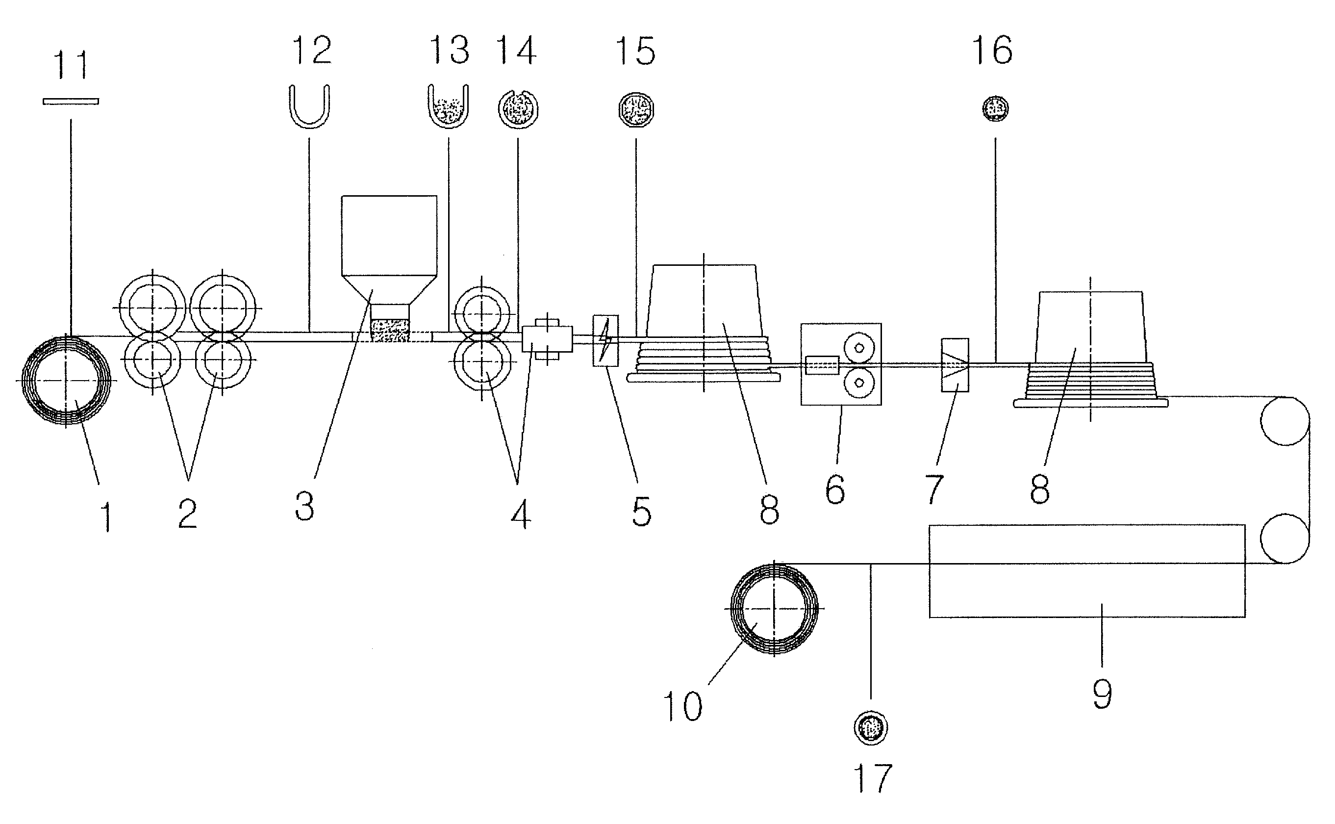
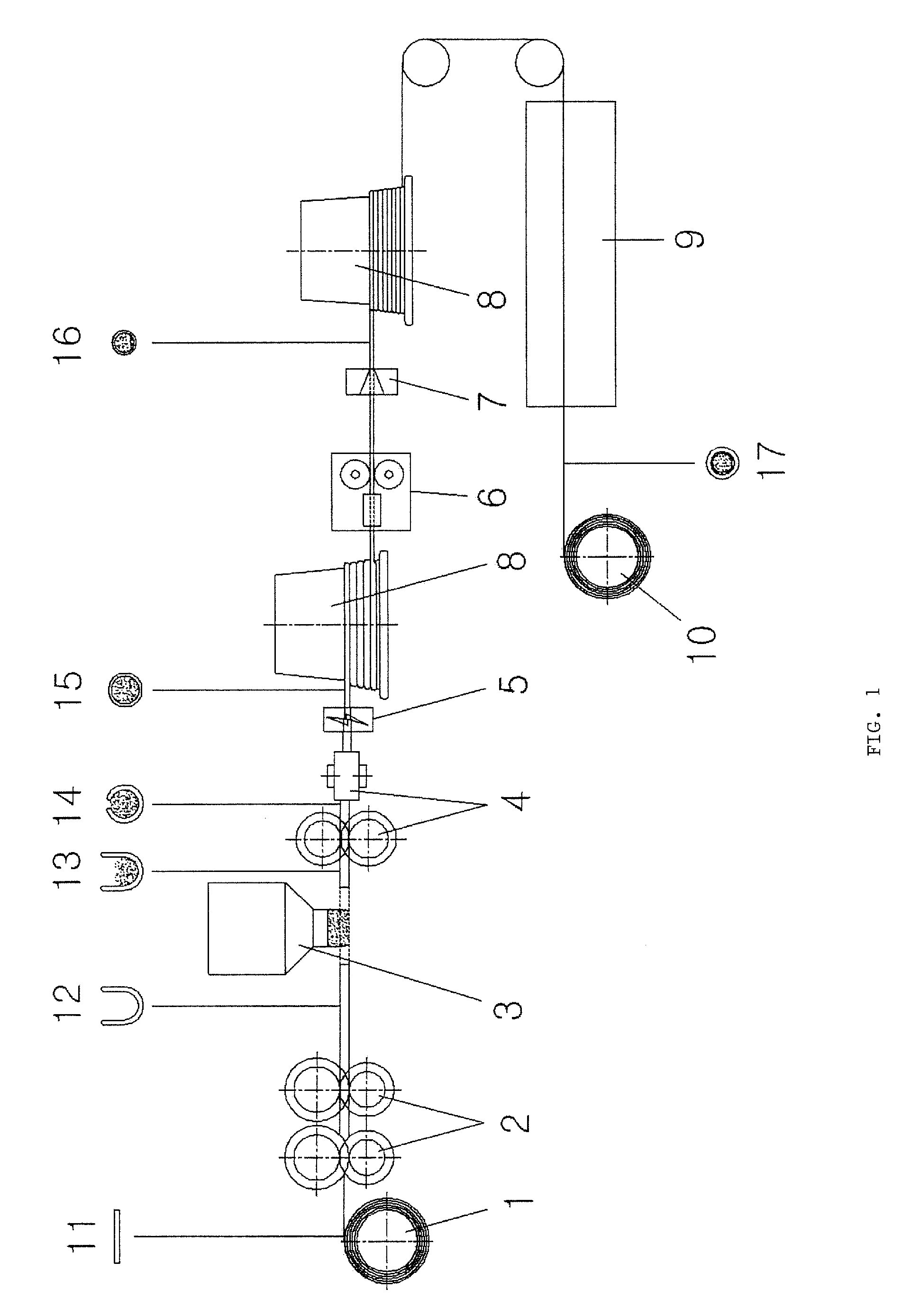
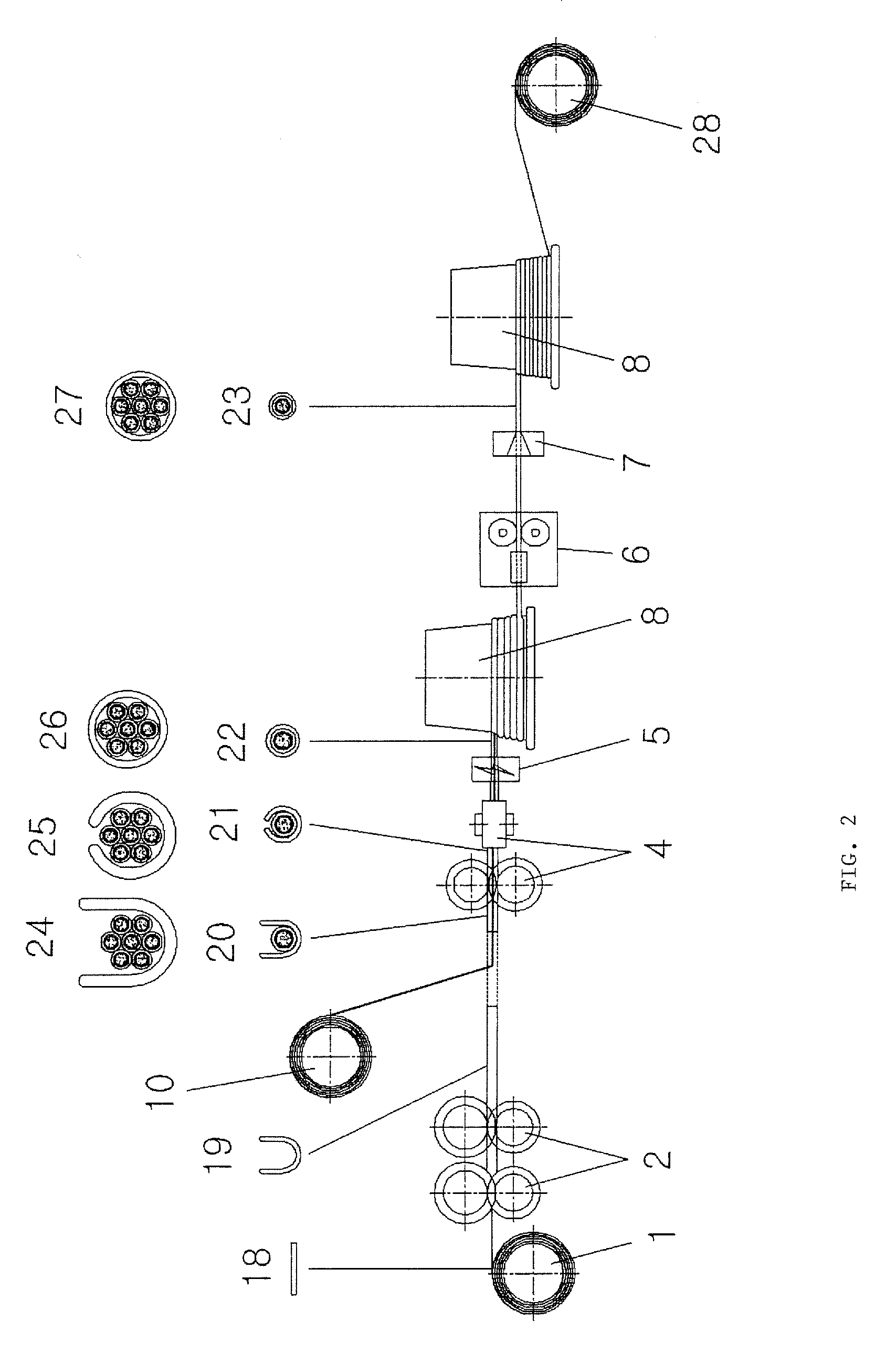
[0024]In an embodiment of the present invention, a method of manufacturing a MgB2 superconducting core wire can include: supplying a covering material formed as a metal strip; forming the covering material into a U-shaped tube to contain MgB2 superconducting powder; filling the MgB2 superconducting powder into the U-shaped covering material; forming the filled covering material into a tube shape; welding a seamed portion of the formed tube; rolling or drawing the welded tube; sintering the superconducting powder in the rolled or drawn tube or heat treating the tube to alleviate work hardening; and cleaning a work surface of the wire and then plating the wire with a conductive material to obtain a stabilizer.

Problems solved by technology

However, the bismuth-based superconducting wire has problems related to its crystalline structure, making it difficult to implement the wire's critical current density at more than 100,000 A / cm2 in a magnetic field at a liquid nitrogen temperature of 77K.
If a selected covering material has high electrical resistance, the superconducting state may be broken due to an increase in temperature caused by internal and external factors.
In order to inhibit occurrence of this phenomenon, a metal material (a stabilizer) having low electrical resistance, high electrical conductivity, and high thermal conductivity can be applied onto the covering material, and the superconducting material can become unstable due to internal and external factors, making it difficult to apply a large amount of current.
In the case of a PIT method, a plurality of processes such as swaging, drawing, wire drawing, rolling, and heat treatment are repeated, thereby making it difficult to evenly control the processes.
In particular, when the covering material is formed of copper, silver, and an alloy thereof having good electrical conductivity, MgB2 superconducting powder cannot be uniformly pressurized due to high flexibility of the metals and high hardness of the MgB2 superconducting powder, thereby producing a core wire having non-uniform critical current density.
In addition, the high cost of the silver and the alloy decreases economical efficiency.
However, since the basic manufacturing method is similar to the conventional method requiring a large number of processes, such as plasticization and heat treatment, and limiting the length of the tube, it is difficult to increase productivity and elongate a wire sufficiently to adapt the wire to various fields.
However, when the tube is used, a continuous process is difficult to perform, thereby causing inefficiency.
Also, when the tube forming is used, equipment and processes similar to manufacturing the conventional superconducting core wire are separately required, meaning that additional plasticization and heat treatment are required, thereby decreasing critical current characteristics and manufacturing efficiency, and increasing manufacturing costs.

Method used


Image

  • Method of Manufacturing MgB2 Superconducting Wire
  • Method of Manufacturing MgB2 Superconducting Wire
  • Method of Manufacturing MgB2 Superconducting Wire

Examples


example 1

[0048]Stainless steel 304L selected as a covering material was continuously supplied to form a U-shaped tube using a primary tube forming roller, and MgB2 superconducting powder was filled in the tube. Then, an O-shaped tube was formed using a secondary tube forming roller, and a seamed portion of the tube was welded by gas tungsten arc welding (GTAW). Next, the tube was rolled using a CRD to reduce the diameter of the tube, and heat treatment was performed to alleviate work hardening.

[0049]At this time, due to work hardening characteristics of the stainless steel 304L, heat treatment was performed on the stainless steel 304L to inhibit inferior quality of the products.

[0050]Then, the tube passed through an electroplating bath, in which copper ions were melted, to form a copper plated layer on a surface of the tube, thereby obtaining a MgB2 superconducting core wire wound on the spool.

[0051]Next, Monel 400 formed of a Ni—Cu alloy was selected as a reinforcement material to manufactu...


PUM

PropertyMeasurementUnit
Temperatureaaaaaaaaaa
Volumeaaaaaaaaaa

Abstract

A method of manufacturing a superconducting wire is provided. A MgB2 superconducting wire capable of obtaining a stabilizer through an inexpensive process can have high critical current density and magnetic field characteristics without separate plastic. A seamed portion of the wire can be welded to make it possible to plate the wire with conductive materials and inhibit a decrease in quality of superconducting powder. It is possible to obtain a stabilizer without inserting the superconducting powder into a tube.

Description

CROSS-REFERENCE TO RELATED APPLICATION[0001]The present application claims the benefit under 35 U.S.C. §119 of Korean Patent Application No. 10-2007-0068129, filed Jul. 6, 2007, which is hereby incorporated by reference in its entirety.BACKGROUND OF THE INVENTION[0002]1. Field of the Invention[0003]The present invention relates to a method of manufacturing a superconducting wire, and more particularly, a method of manufacturing a MgB2 superconducting wire.[0004]2. Background of the Related Art[0005]Generally, superconductivity is a phenomenon where a large amount of current can be supplied with minimal to no energy loss or electric resistance that can generate heat. Using the superconductivity phenomenon, it is possible to fabricate small-volume machines employing a high level of power with little to no energy loss. Superconductivity is leading the way with revolutionary changes in many fields, such as electricity / electronics, mechanics, atomic energy, medicine, and shipbuilding.[00...

Claims


Application Information

Patent Timeline
IPC IPC(8): H01L39/24
CPCY10T29/49014H01L39/2487H10N60/0856H01B12/02
Inventor LEE, YOON SANGCHUNG, WOO HYUN
Owner KISWEL LTD
Learn More