Polymer, Method For Producing the Polymer, Optical Film, and Image Display Device

a technology of optical film and polymer, which is applied in the direction of photomechanical equipment, instruments, natural mineral layered products, etc., can solve the problems of poor heat resistance of plastic substrates, reduced conductivity and gas-barrier properties of layers, and increased cost, etc., to achieve the effect of improving the properties of plastic substrates

Inactive Publication Date: 2008-10-09
FUJIFILM CORP
View PDF8 Cites 6 Cited by
  • Summary
  • Abstract
  • Description
  • Claims
  • Application Information

AI Technical Summary

Benefits of technology

[0033]The polyimide in the invention may be copolymerized with any other tetracarboxylic acid than substituted or unsubstituted bicyclo[2.2.1]heptane-2,3,5,6-tetracarboxylic acid, bicyclo[2.2.2]octane-2,3,5,6-tetracarboxylic acid and bicyclic[2.2.2]oct-7-ene-2,3,5,6-tetracarboxylic acid (these are hereinafter referred to as “other tetracarboxylic acids”), not detracting from the effect of the invention. When the polyimide is copolymerized with any other tetracarboxylic acid, then the molar percentage of the other tetracarboxylic acid in all the constitutive tetracarboxylic acids, as represented by x, preferably falls within a range of 0.01≦x≦70 mol %, more preferably 0.01≦x≦50 mol %, even more preferably 0.01≦x ≦30 mol %.
[0034]In addition, the polyimide in the invention may also be copolymerized with any other diamine than the aromatic diamine that contains the linking group of formula (2) (hereinafter these are referred to as “other diamines”), for the purpose of improving the properties thereof such as the heat resistance and the transparency thereof not detracting from the effect of the invention. When the polyimide is copolymerized with any other diamine, then the molar percentage of the other diamine in all the constitutive diamines, as represented by y, preferably falls within a range of 0.01≦y≦80 mol %, more preferably 0.01≦y≦70 mol %, even more preferably 0.01≦y ≦50 mol %.
[0035]Examples of the other tetracarboxylic acids are mentioned below in the form of carboxylic acid structures corresponding to them.
[0036]They are (trifluoromethyl)pyromellitic acid, di(trifluoromethyl)pyromellitic acid, diphenylpyromellitic acid, dimethylpyromellitic acid, bis[3,5-di(trifluoromethyl)phenoxy]pyromellitic acid, 2,3,3′,4′-biphenyltetracarboxylic acid, 3,3′,4,4′-biphenyltetracarboxylic acid, 3,3′,4,4′-tetracarboxydiphenyl ether, 2,3′,3,4′-tetracarboxydiphenyl ether, 3,3′,4,4′-benzophenonetetracarboxylic acid, 2,3,6,7-tetracarboxynaphthalene, 1,4,5,8-tetracarboxynaphthalene, 3,3′,4,4′-tetracarboxydiphenylmethane, 3,3′,4,4′-tetracarboxydiphenyl sulfone, 2,2-bis(3,4-dicarboxyphenyl)propane, 2,2-bis(3,4-dicarboxyphenyl)hexafluoropropane, 5,5′-bis(trifluoromethyl)-3,3′,4,4′-tetracarboxybiphenyl, 2,2′,5,5′-tetrakis(trifluoromethyl)-3,3′,4,4′-tetracarboxybiphenyl, 5,5′-bis(trifluoromethyl)-3,3′,4,4′-tetracarboxydiphenyl ether, 5,5′-bis(trifluoromethyl)-3,3′,4,4′-tetracarboxybenzophenone, bis[(trifluoromethyl)dicarboxyphenoxy]benzene, bis(dicarboxyphenoxy)bis(trifluoromethyl)benzene, bis(dicarboxyphenoxy)tetrakis(trifluoromethyl)benzene, 3,4,9,10-tetracarboxyperylene, 2,2-bis[4-(3,4-dicarboxyphenoxy)-phenyl]propane, cyclobutanetetracarboxylic acid, cyclopentanetetracarboxylic acid, 2,2-bis[4-(3,4-dicarboxy-phenoxy)phenyl]hexafluoropropane, bis(3,4-dicarboxyphenyl)-dimethylsilane, 1,3-bis(3,4-dicarboxyphenyl)tetramethyl-disiloxane, difluoropyromellitic acid, 1,4-bis(3,4-dicarboxytrifluorophenoxy)tetrafluorobenzene, 1,4-bis(3,4-dicarboxytrifluorophenoxy)octafluorobiphenyl, pyrazine-2,3,5,6-tetracarboxylic acid, pyrrolidine-2,3,4,5-tetra-carboxylic acid, thiophene-2,3,4,5-tetracarboxylic acid, 9,9-bis(3,4-dicarboxyphenyl)fluorene.
[0038]They are p-phenylenediamine, m-phenylenediamine, o-phenylenediamine, 2,2-bis[4-(4-aminophenoxy)phenyl]-propane, 2,2-bis[4-(4-aminophenoxy)phenyl]hexafluoropropane, 4,4′-bis(4-aminophenoxy)biphenyl, bis[4-(4-aminophenoxy)-phenyl]sulfone, bis[4-(3-aminophenoxy)phenyl]sulfone, 4,4′-diaminodiphenyl ether, 3,4′-diaminodiphenyl ether, bis[4-(4-aminophenoxy)phenyl]ether, 1,4-bis(4-aminophenoxy)benzene, 1,3-bis(4-aminophenoxy)benzene, 2,2-bis(4-aminophenyl)propane, 2,2-bis(4-aminophenyl)hexafluoropropane, 4,4′-diaminobenzophenone.
[0039]For obtaining the polyimide from tetracarboxylic acid and diamine such as those mentioned above, there may be employed a one-stage polymerization method that comprises polymerizing a tetracarboxylic acid (especially a tetracarboxylic acid anhydride) and a diamine in an organic polar solvent at a high temperature to give a polyimide; and a two-stage polymerization method that comprises reacting a tetracarboxylic acid (especially a tetracarboxylic acid anhydride) and a diamine at a low temperature to give a polyamidic acid, then applying the acid onto a substrate to form a film thereon, and imidating it at a high temperature. The polymerization temperature in the one-stage polymerization method may be from 100 to 250° C., preferably from 150 to 200° C.; and the polymerization time may be from 0.5 to 20 hours, preferably from 1 to 15 hours. After the polymerization, the solution may be directly applied onto a substrate such as a glass plate or a metal plate and the solvent may be evaporated away to produce a polyimide film. If desired, the polymerization solution may be reprecipitated in a bad solvent such as methanol or water, then the solid precipitate may be dissolved in a good solvent, and the resulting solution may be applied onto a substrate such as a glass plate or a metal plate and the solvent may be evaporated away to produce a polyimide film. If the imidation is insufficient, then the film formed on the substrate may be heated at a temperature around the glass transition temperature of the polymer to attain the imidation, whereby the intended polyimide film may be obtained. In the two-stage polymerization method, the polyamidic acid production may be effected at a temperature of from 0 to 120° C., preferably from 15 to 120° C., more preferably from 20 to 110° C. for a period of time of from 0.5 to 100 hours, preferably from 1 to 70 hours, and after the polymerization, the resulting solution may be directly applied onto a substrate such as a glass plate or a metal plate and heated at 200° C. to 350° C. whereby the polymer may be imidated and the intended polyimide film may be thus produced.

Problems solved by technology

However, even using such heat-resistant plastics could not still give plastic substrates of satisfactory heat resistance.
Specifically, when a conductive layer is formed on such a heat-resistant plastic substrate and then it is exposed to a high temperature not lower than 150° C. for imparting an alignment film thereto, then there occurs a problem in that the conductivity and the gas-barrier property of the layer may greatly lower and worsen.
However, these methods variously proposed for forming polycrystalline silicon films for TFT at 300° C. or lower are still problematic in that their constitutions and the apparatus they require are complicated and expensive, and therefore plastic substrate resistant to heat at 300° C. to 350° C. are desired.
In addition, the process of fabricating a polycrystalline silicon film for TFT requires some high-temperature processing steps, and therefore, even plastic substrates of good heat resistance may still have some problems if their linear thermal expansion coefficient is large in that the transparent conductive layer may peel from the substrate owing to its deformation or the resistance value of the conductive layer may increase.
The polyimide film has good transparency, but is not still satisfactory in heat resistance for forming a high-quality polycrystalline silicon film for TFT.
Accordingly, it has heretofore been desired to develop an optical film having both good heat resistance and good optical properties, but no one has heretofore succeeded in obtaining a satisfactory optical film

Method used


Image

  • Polymer, Method For Producing the Polymer, Optical Film, and Image Display Device
  • Polymer, Method For Producing the Polymer, Optical Film, and Image Display Device
  • Polymer, Method For Producing the Polymer, Optical Film, and Image Display Device

Examples


example 1

1. Production of Films

(1) Production of Film P-1:

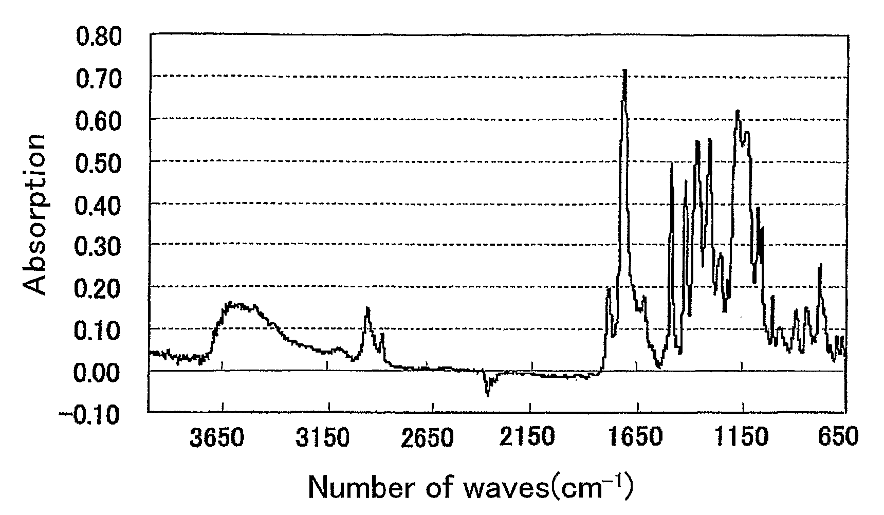
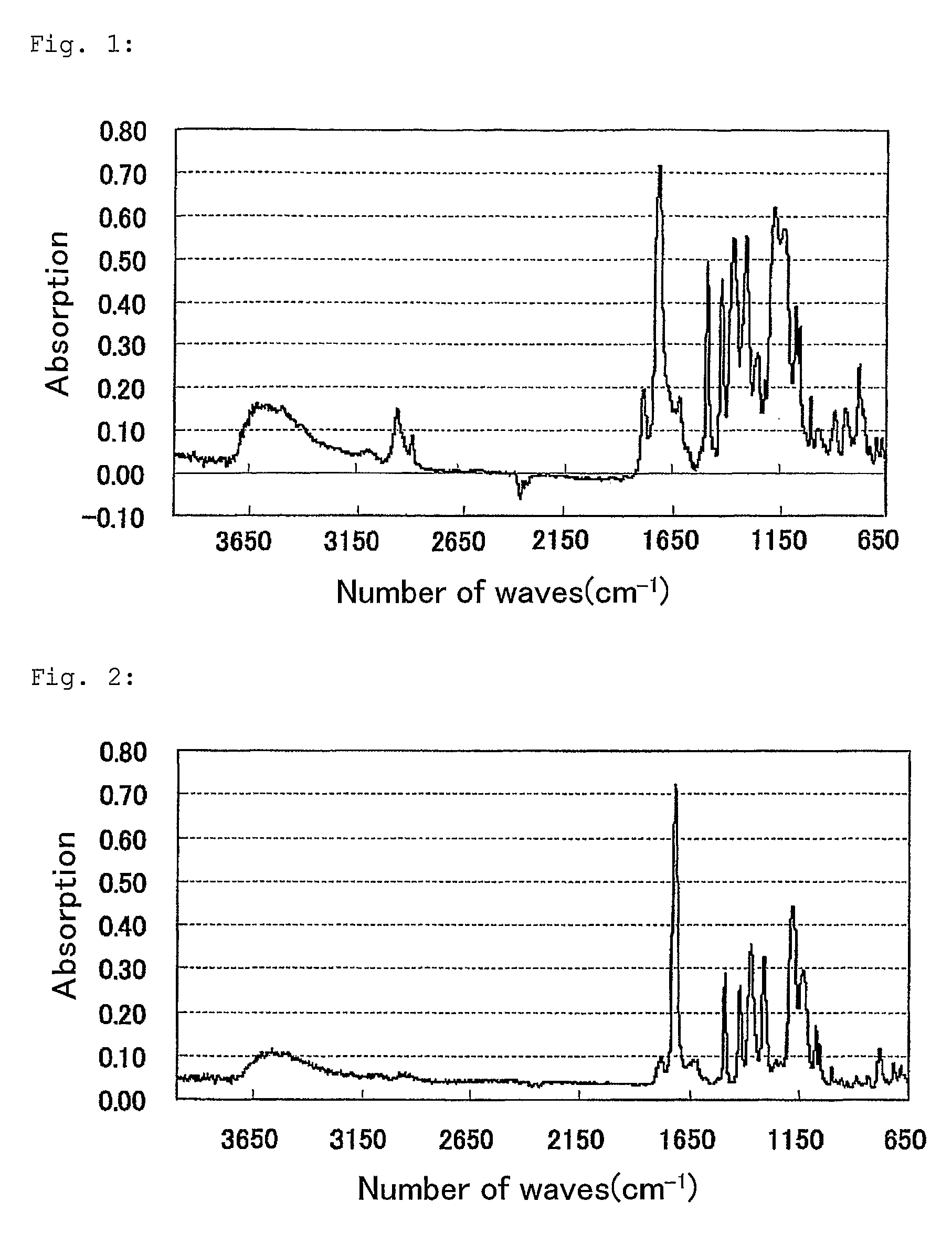
[0086]32 g of 2,2′-bis(trifluoromethyl)-4,4′-diaminobiphenyl was put into a reactor equipped with a thermometer, a stirrer and a nitrogen-introducing duct, and this was dissolved in 230 g of N-methyl-2-pyrrolidone. Then, 25 g of bicyclo[2.2.2]octane-2,3,5,6-tetracarboxylic acid was gradually added to it at 15° C. This was reacted at 30° C. for 1 hour, then at 70° C. for 1 hour and further at 100° C. for 1 hour, and this gave a transparent solution. Next, as additives, 6.2 g of triphenyl phosphite and 16 g of pyridine were gradually and dropwise added to it, and this was stirred at 100° C. for 0.5 hours, then at 130° C. for 0.5 hours, at 150° C. for 0.5 hours and at 170° C. for 5 hours. Next, the solution was kept cooled, and then reprecipitated in a mixed solution of 2 liters of methanol and 2 liters of water to obtain a polymer. This was filtered, the deposit was dried and again dissolved in N,N-dimethylacetamide. Using a film applic...

example 2

Production of Stretched Films

1. Monoaxial Stretching

[0099]For confirming the fact that the stretched polymer of the invention shows extremely lowered thermal expansiveness, the polymer of the invention was stretched.

[0100]A film sample (2.0 cm×7.0 cm piece) is prepared, and monoaxially stretched at a pulling rate of 200 mm / min, using a tensilon (Orientec's Tensilon RTC-1210A). Three samples are tried in one test, and their data are averaged. (The chuck-to-chuck distance is 5 cm, and the draw ratio is 1.3 times.)

[0101]The polymer P-1 was dissolved in N,N-dimethylacetamide in a ratio of 20% by mass to prepare a dope. This was cast on a glass plate, using a doctor blade, and dried at 80° C. Before completely dried, this was peeled from the glass plate, cut into a piece having a size of 20 mm×70 mm, and stretched with a tensilon. The stretching condition was as follows: The resin temperature was 250° C., the pulling rate was 200 mm / min, the chuck-to-chuck distance was 50 mm, and the dra...

example 3

Formation of Gas-Barrier Layer and Transparent Electrode Layer

1. Formation of Gas-Barrier Layer

[0105]A target of Si was sputtered onto both surfaces of the optical film samples P-1, P-2, P-21 and P-22 fabricated in the above, according to a DC magnetron sputtering process under a vacuum of 500 Pa in an Ar atmosphere with oxygen being introduced into the chamber. The pressure was 0.1 Pa and the output power was 5 kW. A gas-barrier layer was thus formed, and it had a thickness of 60 nm. The water vapor permeation through the optical film samples with a gas-barrier layer formed on both surfaces thereof was at most 0.1 g / m2·day, measured at 40° C. and at a relative humidity of 90%; and the oxygen permeation through them was at most 0.1 ml / m2 ·day, measured at 40° C. and at a relative humidity of 90%.

2. Formation of Transparent Conductive Layer

[0106]While the gas-barrier layer-coated optical film samples were heated at 300° C., a target of ITO (In2O3, 95 mas. %; SnO2, 5 mas. %) was sputt...


PUM

PropertyMeasurementUnit
Thicknessaaaaaaaaaa
Thicknessaaaaaaaaaa
Glass transition temperatureaaaaaaaaaa

Abstract

An optical film having a recurring unit of the following formula (1) with good heat resistance and good optical properties:wherein X represents a divalent linking group containing a monocyclic or condensed polycyclic aromatic ring; Y represents a methylene group, an ethylene group or an ethenylene group; and X is represented by the following formula (2):wherein R1 and R2 each represent a halogen atom, an alkyl group, an alkoxy group or an aryl group; and m and n each indicate from 0 to 4.

Description

TECHNICAL FIELD[0001]The present invention relates to a polymer having good heat resistance and good optical properties, to a method for producing the polymer, to an optical film and to an image display device of good display quality that comprises the optical film.BACKGROUND ART[0002]Recently, in the field of flat panel displays of, for example, liquid-crystal display devices and organic electroluminescent devices (hereinafter referred to as “organic EL devices”), using plastics in place of glass substrates is under investigation from the demand for improving the breakage resistance thereof and for reducing the weight and the thickness thereof. In particular, in the display devices for mobile information communication instruments of, for example, mobile information terminals such as mobile telephones, pocketsize personal computers and laptop personal computers, there is a great demand for plastic substrates.[0003]Plastic substrates for use in the field of plat panel displays must b...

Claims


Application Information

Patent Timeline
IPC IPC(8): B32B27/00C08F26/06
CPCC08G73/22C09D179/08G02F1/133305G03F7/0007C08G73/00G03F7/023
Inventor AIKI, YASUHIROISHIZUKA, TAKAHIRO
Owner FUJIFILM CORP
Why Eureka
Try Eureka