
Nonaqueous electrolyte battery, battery pack and vehicle

a technology of nonaqueous electrolyte and battery pack, which is applied in the direction of batteries, non-aqueous electrolyte cells, hybrid vehicles, etc., can solve the problems of nonaqueous electrolyte batteries having protective circuits and reducing discharge capacity, and achieves improved corrosion resistance, enhanced strength, and higher strength

Active Publication Date: 2008-10-02
KK TOSHIBA
View PDF8 Cites 58 Cited by
  • Summary
  • Abstract
  • Description
  • Claims
  • Application Information

AI Technical Summary

Benefits of technology

[0048]Irregular distribution of the overdischarge depth in the in-plane direction on the surface of the positive electrode tends to be expanded in accordance with increase in the battery size. Therefore, a satisfactory effect of the invention may be obtained by employing the configuration of this embodiment when the total area An of the negative electrode current corrector is 500 cm2 or more.
[0049]The negative electrode, positive electrode and nonaqueous electrolyte will be described below.
[0051]The negative electrode includes a negative electrode current collector and a negative electrode layer retained on one surface or both surfaces of the negative electrode current collector and containing a negative electrode active material, a conductive agent and a binder.
[0052]The negative electrode current collector is formed of an aluminum foil or an aluminum alloy foil. The purity of aluminum is preferably 99.5% or more, more preferably 99.99% or more for improving the corrosion resistance and for enhancing the strength. The aluminum alloy preferably contains at least one element selected from the group consisting of iron, magnesium, zinc, manganese and silicon in addition to aluminum. For example, a higher strength than aluminum may be obtained by using Al—Fe base alloys, Al—Mn base alloys and Al—Mg base alloys. On the other hand, the content of transition metals such as nickel and chromium in aluminum and aluminum alloys is preferably 100 ppm or less (including 0 ppm). For example, Al—Cu base alloys are not suitable for the current collector since corrosion resistance is poor, although the strength increases. The content of aluminum in the aluminum alloy is desirably 99.5% by weight or more.
[0053]The thickness of the negative electrode current collector is preferably from 10 μm or more to 30 μm or less. Cycle life may be decreased when the thickness of the negative electrode current collector is less than 10 μm since pin holes and cracks tend to be generated.
[0054]The specific capacitance of the negative electrode current collector is desirably less than 20 μF / cm2. The surface of the negative electrode current collector is preferably coated with a dense alumina layer without performing surface roughening. The negative electrode current collector having the above-mentioned specific capacitance and surface configuration has a high tensile strength with few pinholes and cracks. Accordingly, the negative electrode current collector is prevented from being broken when the negative electrode current collector is applied a large pressing pressure. Therefore, a high density negative electrode may be obtained by using a negative electrode active material with an average particle diameter of 1 μm or less. Consequently, a nonaqueous electrolyte battery having a high capacity and being excellent in cycle performance under conditions of rapid charge and high power discharge may be provided. The more preferable range of specific capacitance is from 0.01 μF / cm2 or more to 15 μF / cm2 or less.

Problems solved by technology

However, the discharge capacity rapidly decreases when the nonaqueous electrolyte battery having the current collector made of copper foil is overdischarged since a dissolving reaction of the copper foil is accelerated by an increase in potential of the negative electrode.
However, the nonaqueous electrolyte battery having the protective circuit was disadvantage in terms of the energy density.
However, the nonaqueous electrolyte battery described in JP-A 2002-42889 (KOKAI) involves a problem in the performance under a high temperature environment.

Method used


Image

  • Nonaqueous electrolyte battery, battery pack and vehicle
  • Nonaqueous electrolyte battery, battery pack and vehicle
  • Nonaqueous electrolyte battery, battery pack and vehicle

Examples


first embodiment

[0037]The inventors of the invention have found, through intensive studies, that the high temperature performance may be improved by permitting a nonaqueous electrolyte battery using a negative electrode active material having a lithium ion absorption potential of 0.4 V (vs. Li / Li+) or more to have the configurations (1) and (2):

[0038](1) both the positive electrode current collector and negative electrode current collector are formed of aluminum or an aluminum alloy; and

[0039](2) the total area and specific capacitance of the positive electrode current collector are made to be larger than those of the negative electrode current collector.

[0040]Specifically, the invention provides a nonaqueous electrolyte battery being excellent in charge-discharge cycle performance under a high temperature environment and being able to obtain a high capacity recovery rate when kept under the above-mentioned condition.

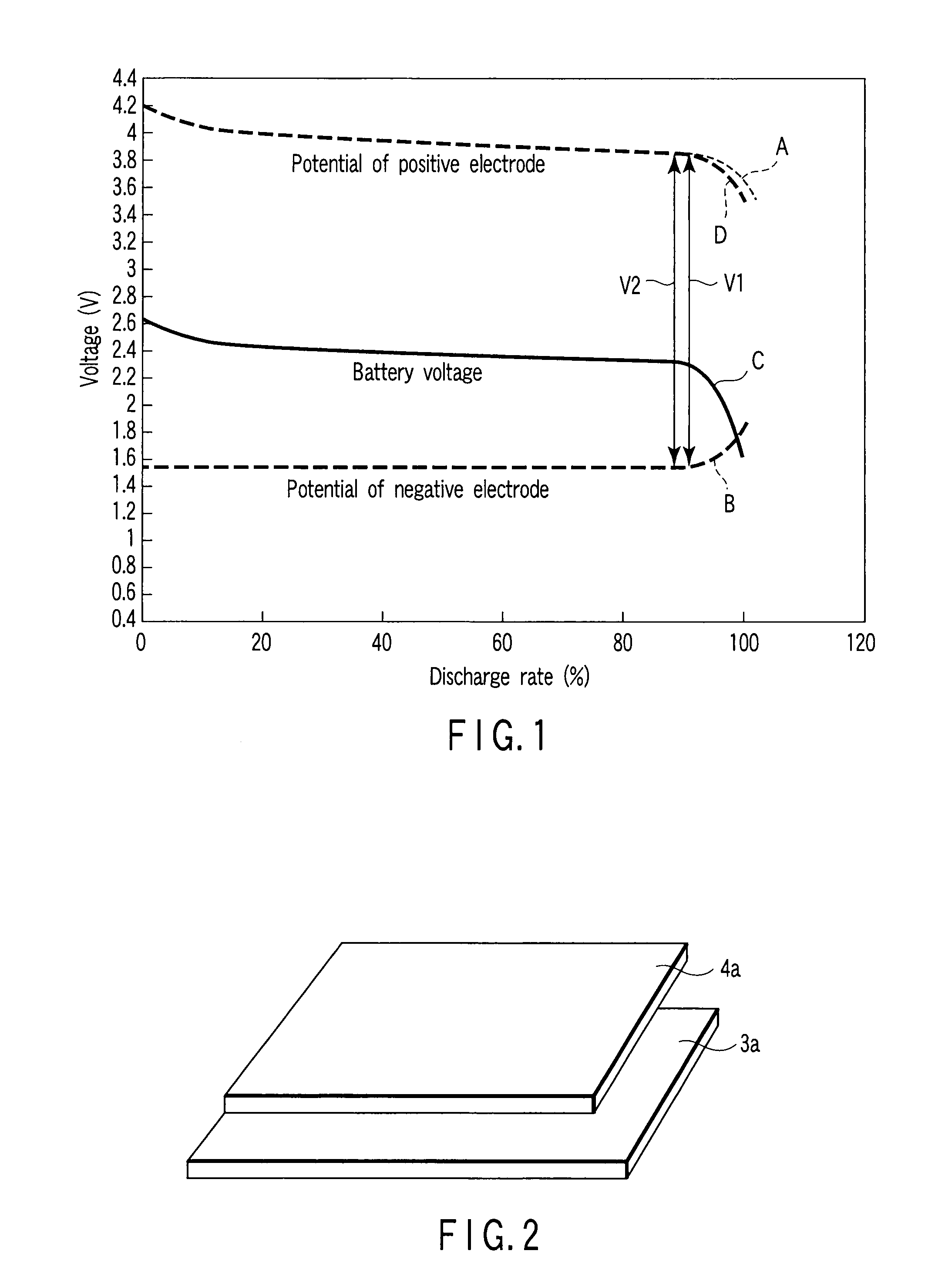
[0041]FIG. 1 shows a discharge voltage curve of the nonaqueous electrolyte battery...

second embodiment

[0123]The battery pack according to the second embodiment comprises the nonaqueous electrolyte battery according to the first embodiment as unit cell. A plurality of the unit cells may be used. The unit cells are electrically connected in series or parallel to form an assembled battery.

[0124]The unit cell according to the first embodiment is suitable for use as the assembled battery, while the battery pack according to the second embodiment is excellent in charge / discharge cycle performance under high temperature environments. These features will be described below.

[0125]Since the nonaqueous electrolyte battery according to the first embodiment is excellent in charge / discharge cycle performance under high temperatures, any irregularity of charge / discharge cycle performance among the unit cells can be largely suppressed. Accordingly, the battery pack according to the second embodiment can improve the charge / discharge cycle performance at high temperatures. Since battery voltage chang...

third embodiment

[0138]The vehicle according to the third embodiment comprises the battery pack according to the second embodiment. A large current of about 10 C usually flows in vehicle-mounted battery packs. Since the unit cell of the first embodiment can suppress deterioration due to overdischarge of the positive electrode at a large current discharge, it is also excellent in charge / discharge cycle performance under a large current. Further, since any irregularity of the charge / discharge cycle life among the unit cells can be reduced, the battery pack according to the second embodiment is excellent in cycle performance under a large current. Accordingly, the vehicle according to the third embodiment is excellent in performance of driving source. The vehicle as used herein includes two- to four-wheel hybrid electric cars, from two- to four-wheel electric cars, and motor-assisted bicycles.

[0139]FIGS. 11 to 13 show various type of hybrid vehicles in which an internal combustion engine and a motor dr...


PUM


Abstract

A nonaqueous electrolyte battery includes a negative electrode and a positive electrode. The negative electrode includes a negative electrode current collector and a negative electrode active material having a lithium ion absorption potential of 0.4 V (vs. Li / Li+) or more. The negative electrode current collector is made of aluminum or an aluminum alloy. The positive electrode includes a positive electrode current collector and a positive electrode active material. The positive electrode current collector has a total area and specific capacitance larger than those of the negative electrode current collector, and is made of aluminum or an aluminum alloy.

Description

CROSS-REFERENCE TO RELATED APPLICATIONS[0001]This application is based upon and claims the benefit of priority from prior Japanese Patent Application No. 2007-082697, filed Mar. 27, 2007, the entire contents of which are incorporated herein by reference.BACKGROUND OF THE INVENTION[0002]1. Field of the Invention[0003]The present invention relates to a nonaqueous electrolyte battery, and a battery pack and a vehicle using the nonaqueous electrolyte battery.[0004]2. Description of the Related Art[0005]Research and development of a nonaqueous electrolyte battery comprising a negative electrode containing metallic lithium, a lithium alloy, a lithium compound or carbonaceous materials have been actively advancing as a high energy density battery or high power density battery. A lithium ion battery comprising a positive electrode containing LiCoO2 or LiMn2O4 as an active material and a negative electrode containing a carbonaceous material for absorption / release of lithium ions has been put...

Claims


Application Information

Patent Timeline
IPC IPC(8): H01M6/14H01M4/46H01M4/58B60K1/04H01M4/131H01M4/485H01M4/505H01M4/525H01M4/66H01M10/0525
CPCB60K1/04Y02T90/121B60K6/46B60K6/48B60K2001/0416B60K2001/0433B60K2001/0438B60L11/1801B60L11/185B60L11/1859B60L11/1862B60L11/1872B60L2200/12B60W2300/36B60Y2200/12H01M4/362H01M4/485H01M4/505H01M4/525H01M4/661H01M10/0525H01M2004/021Y02E60/122Y02T10/6217Y02T10/6221Y02T10/7005Y02T10/7011Y02T10/7044Y02T10/705Y02T90/128Y02T90/14B60K6/28B60L50/53B60L53/11B60L58/25Y02E60/10Y02T10/62Y02T10/70Y02T10/7072Y02P70/50B60L58/13B60L58/14H01M4/13H01M4/366H01M4/62H01M4/662H01M10/42H01M2010/4292H01M2220/20Y02T90/12
Inventor TAKAMI, NORIOINAGAKI, HIROKIMATSUNO, SHINSUKE
Owner KK TOSHIBA
Learn More