Tomographic device and method therefor

a tomographic device and image reconstruction technology, applied in tomography, instruments, applications, etc., can solve the problems of reducing affecting the diagnostic accuracy of tomographic devices, and complicated image reconstruction methods therefor

Active Publication Date: 2007-07-19
FUJIFILM HEALTHCARE CORP
View PDF7 Cites 15 Cited by
  • Summary
  • Abstract
  • Description
  • Claims
  • Application Information

AI Technical Summary

Benefits of technology

[0020] Another feature of the tomographic device according to the present invention is that in the tomographic device provided with the above mentioned feature, the processing means approximately calculates the addresses of the projection data to be back projected through an interpolation processing based on a plurality of representative addresses of detecting means in the image data segment region. In other words, in the back projection processing for every image data segment, the addresses of the detecting means on the extracted projection data segment are calculated through an interpolation by making use of the plurality of the limited representative addresses of the detecting means on the image data segment region. Thereby, the address calculation of the detector means in the back projection processing can be performed in high speed.

Problems solved by technology

In the case of MDCT, since every X-ray detector rows locate in different slanting angles with respect to the circumferential revolving axis direction, parameters for specifying the projection data increase such as channel, row and slanting angle and now the image reconstruction methods therefor are complicated and diversified.
However, since the weighted back projection method for helical correction uses an algorithm which neglects beam slanting (cone angle) of X-rays in the circumferential revolving direction, an image quality of MDCTs with detectors of more than 16 rows is significantly deteriorated due to the influence of the cone angle, which reduces the diagnostic accuracy of tomographic devices.
For this reason, the application of the weighted back projection method for helical correction is limited to MDCTs with detectors of about 2˜8 rows of which influence of cone angle is comparatively small.
Among these, although 3-dimensional Radon transformation method is a precise image reconstruction method, an extremely long computing time such as from a few tens minutes to a few hours for obtaining one slice image is required, which prevents practical use thereof.
One of the problems of the image reconstruction method with the highly accurate 3-dimensional back projection method correctly taking into account of the cone angle is to increase significantly the memory amount required when performing the image reconstruction computation in comparison with the 2-dimensional back projection method used for the conventional SDCTs.
Since the high speed memory is generally expensive, the capacity of the high speed memory is mostly small in comparison with that of the inexpensive low speed memory.
In this instance, the processing speed depends on the data transmission speed between the high speed memory and the low speed memory and a processing speed more than the data transmission speed can not be obtained, which causes a delay of the processing time.
Further, even when a dedicated hardware is prepared, like delay depending on the data transmission speed is caused.
As will be understood from the above, in order to obtain a processing speed more than the data transmission speed, the capacity of the expensive high speed memory has to be increased, however, which significantly increases the cost thereof and is not desirable.
Another problem of the image reconstruction method with the highly accurate 3-dimensional back projection method correctly dealing the cone angle is to increase the processing time in comparison with the 2-dimensional back projection method used for the conventional SDCTs.
As will be understood from the above, the 3-dimensional back projection method shows a drawback of accompanying a significant delay for processing data required for the back projection computation due to 2-dimensional addressing and complex addressing.
In particular, the addressing in the row direction in the 3-dimensional back projection method requires to use extremely complicated non-linear functions and simplification by modifying the functions are difficult, which is the great cause of the data processing delay.
However, as disclosed in JP-A-2003-24326, in order to perform back projection on the divided tomographic image reconstruction region stored in the high speed cache memory, all of the projection data thereof are stored in the cache memory, which increases the amount of high speed memory and is not preferable in view of the cost of the device.

Method used


Image

  • Tomographic device and method therefor
  • Tomographic device and method therefor
  • Tomographic device and method therefor

Examples


Embodiment Construction

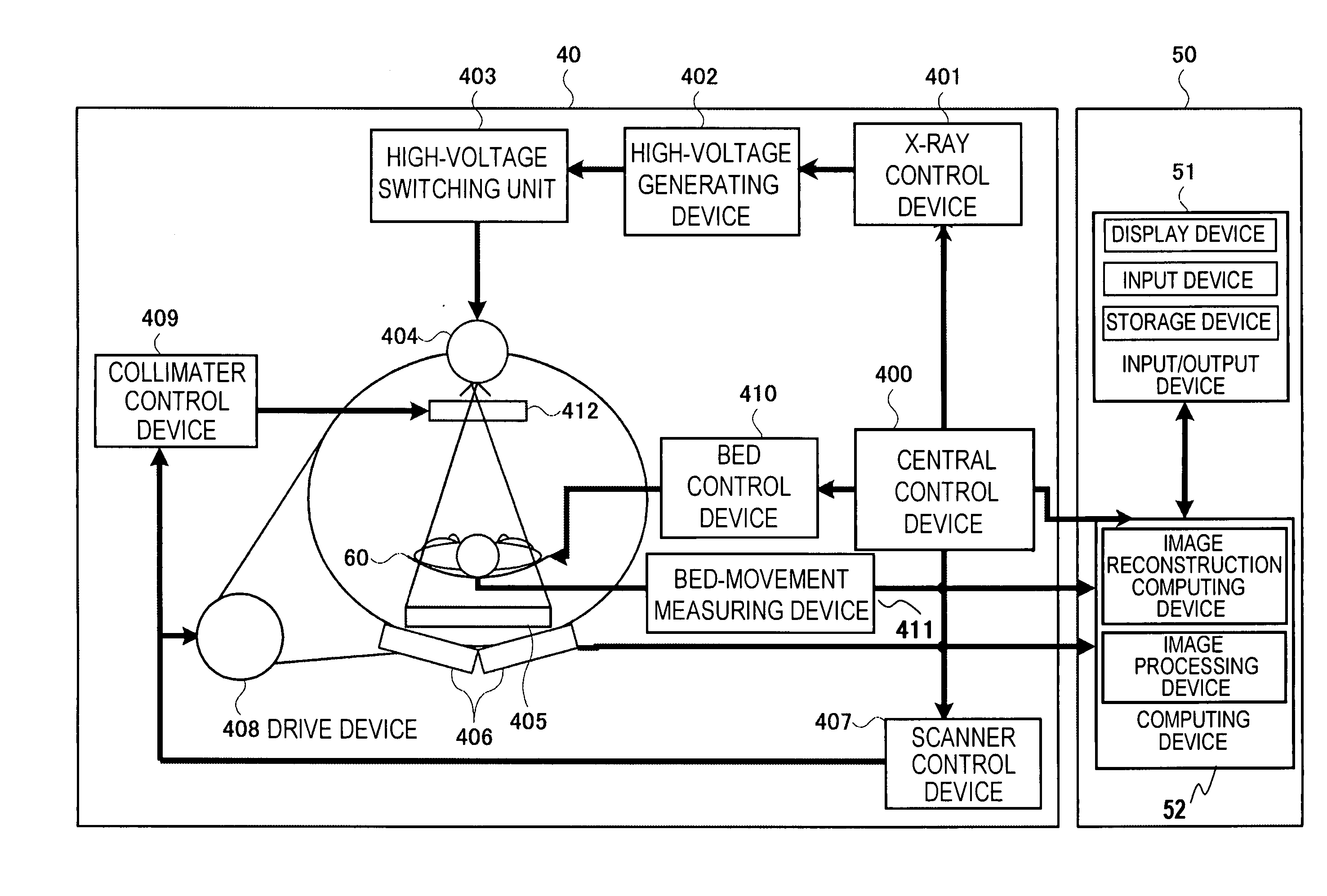
[0029] Herein below, an embodiment of the tomographic device according to the present invention will be explained in detail with reference to the drawings accompanied. FIG. 4 is a diagram showing an entire constitution of an MDCT representing an embodiment of a tomographic device according to the present invention. A scan method of the MDCT is a rotate-rotate method (the third generation) and the MDCT, when roughly sectioned, is constituted by a scanner 40, an operation unit 50 and a bed 60 for moving a subject while setting the same thereon.

[0030] The scanner 40 is constituted such as by a central control device 400, an X-ray control device 401, a high voltage generating device 402, a high voltage switching unit 403, an X-ray generating device 404, an X-ray detector 405, a pre-amplifier 406, a scanner control device 407, a scanner drive device 408, a collimator control device 409, a bed control device 410 and a bed movement measuring device 411. The operation unit 50 is constitute...


PUM


Abstract

An image reconstruction area of a subject is divided into a plurality of image data segments, among projection data obtained by projection, projection data segments necessary for back projection processing are cut out for every image data segments and back projection processing is performed for every image data segments by making use of the cut out projection data segments. Further, detector addresses of the projection data to be used for the back projection processing are obtained from a plurality of limited number of detector addresses within the concerned image data segment region. As a result, a device is realized which permits to produce a high quality tomographic image with high speed by using a small amount of a high speed memory.

Description

FIELD OF THE INVENTION [0001] The present invention relates to a tomographic device and a method therefor, which produces highly accurate tomographic images of a subject from projection data obtained from a radioactive ray source and radioactive ray detector constituted movable relative to the subject in the circumferential revolving direction and in the body axis direction. CONVENTIONAL ART [0002] Recently, a multi detector row computer tomography (herein after will be called as MDCT) has appeared, in which a plurality of detector rows are arranged in the circumferential revolving axis direction. In comparison with a single detector row computer tomography (herein after will be called as SDCT), since the MDCT is provided with detectors in broad width by arranging a plurality of detector element rows along the circumferential revolving axis direction, a broad imaging area can be covered at one time. Further, with the MDCT, when the subject is moved relatively with further higher spe...

Claims


Application Information

Patent Timeline
IPC IPC(8): H05G1/60A61B6/00G01N23/00G21K1/12A61B6/03G06T11/00
CPCA61B6/032A61B6/4085Y10S378/901A61B6/027G06T11/006
Inventor GOTO, TAIGAMIYAZAKI, OSAMUHIROKAWA, KOICHI
Owner FUJIFILM HEALTHCARE CORP
Why Eureka
Try Eureka