
Euv projection lens with mirrors made from material with differing signs for the rise in temperature dependence of the thermal expansion coefficient around the zero transition temperature

a technology of thermal expansion coefficient and projection lens, which is applied in the field of projection objective, can solve the problems of reducing the imaging quality, limiting the resolution limit of the overall system, and scattering light, and achieves the effect of optimizing the characteristic of scattering light and overall imaging quality

Active Publication Date: 2007-02-15
CARL ZEISS SMT GMBH
View PDF5 Cites 46 Cited by
  • Summary
  • Abstract
  • Description
  • Claims
  • Application Information

AI Technical Summary

Benefits of technology

[0018] In the case of such wavelengths of λ<20 nm, the projection objective is constructed with mirrors that reflect the optical radiation. The construction of the projection objective with at least two different mirror materials, the mirrors materials having a very low coefficient of thermal expansion, is advantageous to the effect that it is possible by means of a suitable assignment of the materials to the individual mirrors to balance out or compensate the aberrations of the projection objective with reference to local and global temperature increases such that the resulting effects are minimized. By means of the suitable arrangement of the mirror materials in the projection objective, the projection objective can be operated with relatively strong light sources, something which consequently ensures a higher wafer throughput, and thus a greater productivity. On the other hand, given a fixed thermal load it is possible to relax the requirement placed on the coefficient of thermal expansion (CTE) of the materials, something which consequently enables a higher product yield, and therefore a more economic use of the materials.
[0019] An advantageous refinement of the invention can provide that at least one mirror made from a glass ceramic material and at least one mirror made from an amorphous titanium silicate glass are provided.
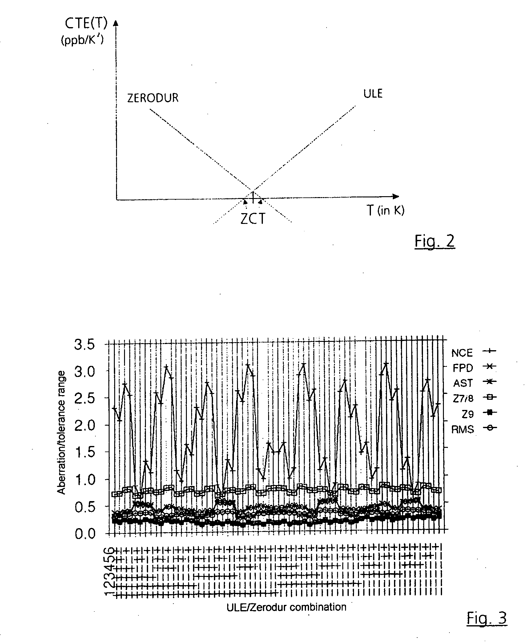
[0020] The coefficients of thermal expansion of a glass ceramic material and an amorphous titanium silicate glass are so small that they can be made to vanish at a specific temperature. By using such materials as mirror substrates in conjunction with correctly allocating the materials to the mirrors, it is possible to minimize aberrations substantially and to improve the overall system quality.

Problems solved by technology

Such errors lead to aberrations, and thereby reduce the imaging quality and restrict the resolution limit of the overall system.
Such spatial wavelengths typically occur in the region between approximately 1 μm and approximately 1 mm, and lead to scattered light within the image field, and therefore to contrast losses in the imaging optics.
Depending on the point of view, the HSFR region leads to light losses by scattering outside the image field of the optics, or owing to interference in the microscopically in-phase superposition of the wavetrain components.
However, silicon has a mechanical anisotropy, and can generally be used only for small mirror sizes, owing to the required monocrystallinity.
Moreover, the comparatively high price of the monocrystalline material is a substantial disadvantage.
When the materials currently used are employed, the system quality that can be achieved with regard to X-ray optics is greatly impaired in different ways.

Method used


Image

  • Euv projection lens with mirrors made from material with differing signs for the rise in temperature dependence of the thermal expansion coefficient around the zero transition temperature
  • Euv projection lens with mirrors made from material with differing signs for the rise in temperature dependence of the thermal expansion coefficient around the zero transition temperature
  • Euv projection lens with mirrors made from material with differing signs for the rise in temperature dependence of the thermal expansion coefficient around the zero transition temperature

Examples


Embodiment Construction

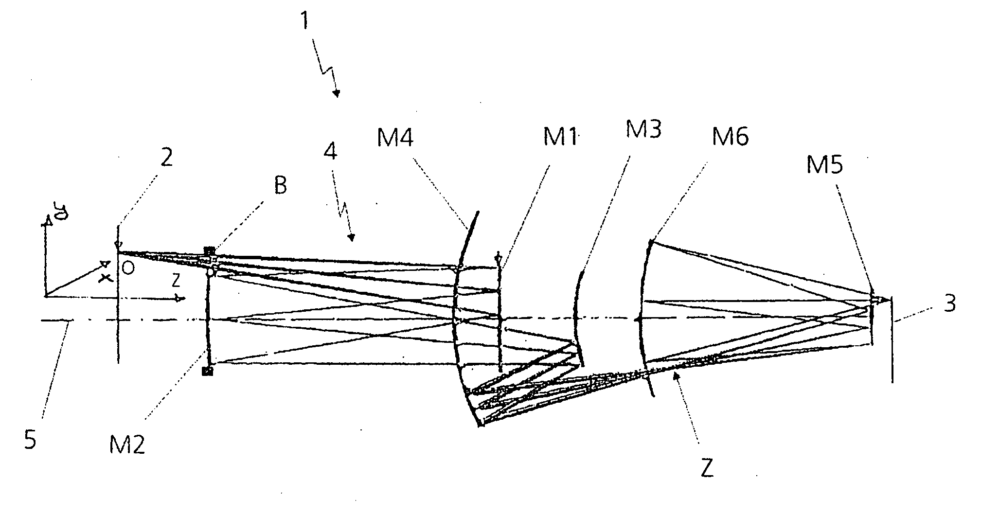
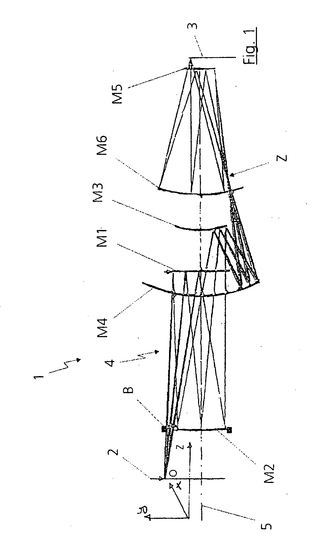
[0027]FIG. 1 shows an exemplary 6-mirror projection objective 1, as known from the prior art, for example in accordance with DE 100 37 870 A1, when used in the EUV region with wavelengths λ2. Here, the object O to be imaged constitutes a mask or a reticle in lithography. The object O is imaged into an image plane 3 via a first mirror M1, a second mirror M2, a third mirror M3, a fourth mirror M4, a fifth mirror M5 and a sixth mirror M6. In lithography, a wafer is arranged in the image plane 3, for example. The six mirrors M1, M2, M3, M4, M5 and M6 are aspheric mirrors, the first mirror M1 being designed as a convex mirror.

[0028] A diaphragm B restricts the beams 4 traversing the system 1. Here, the diaphragm B is located directly on the second mirror M2 or in the direct vicinity of the mirror M2. The overall system is arranged in a fashion centered relative to an optical axis 5, and has a telecentric beam path in the image plane 3. Furthermore, as is clearly evident in FIG. 1, an in...


PUM


Abstract

A projection objective 1 for short wavelengths, in particular for wavelengths λ<157 nm is provided with a number of mirrors M1, M2, M3, M4, M5 and M6 that are arranged positioned precisely in relation to an optical axis 5. The mirrors M1, M2, M3, M4, M5 and M6 have multilayer coatings. At least two different mirror materials are provided which differ in the rise in the coefficient of thermal expansion as a function of temperature in the region of the zero crossing of the coefficients of thermal expansion, in particular in the sign of the size.

Description

BACKGROUND OF THE INVENTION [0001] 1. Field of the Invention [0002] The invention relates to a projection objective for short wavelengths, in particular for wavelengths λ<157 nm, having a number of mirrors that are arranged positioned precisely in relation to an optical axis, and wherein the mirrors have multilayer coatings. The invention also relates to a projection exposure apparatus for EUV lithography as well as an X-ray optical subsystem for X-rays of wavelength λR. [0003] 2. Description of the Related Art [0004] Projection objectives that are used in the extreme ultraviolet region are transradiated with soft X-radiation. Here, the wavelength region is at 10 to 30 nm. The materials previously capable of use for the optics are opaque to the extreme UV light used in the case, the imaging beams no longer being guided through lenses by refraction, but it being possible only to make use of mirrors. The mirrors used should have as high a reflectivity as possible in the EUV region....

Claims


Application Information

Patent Timeline
IPC IPC(8): G06K7/10G02B5/08G02B7/18G03F7/20G21K1/06
CPCB82Y10/00G02B5/0891G02B7/181G02B1/00G03F7/70958G21K1/062G21K2201/065G03F7/70891G03F7/20G02B17/06G21K1/06
Inventor DINGER, UDOEISERT, FRANKKOEHLER, STEFANOCHSE, ANDREASZELLNER, JOHANNESLOWISCH, MARTINLAUFER, TIMO
Owner CARL ZEISS SMT GMBH
Learn More