
Polymer/WUCS mat and method of forming same

Inactive Publication Date: 2007-01-11
OCV INTELLECTUAL CAPITAL LLC
View PDF13 Cites 11 Cited by
  • Summary
  • Abstract
  • Description
  • Claims
  • Application Information

AI Technical Summary

Benefits of technology

[0017] It is an advantage of the present invention that the use of dielectrically dried wet chopped glass fibers provides a cost advantage over conventional low tex roved fiber products which are currently used in dry-laid processes. As a result, the use of dielectrically dried wet chopped glass fibers allows chopped strand mats to be manufactured at lower costs.
[0018] It is another advantage of the present invention that dielectrically drying the wet reinforcement fibers provides an economic method of removing water from the wet reinforcement fibers because the wet reinforcement fibers may be quickly dried at a low net fiber temperature. In addition, dielectrically drying the wet reinforcement fibers enhances fiber-to-fiber cohesion and reduces bundle to bundle adhesion.
[0019] It is a further advantage of the present invention that in removing the water from the wet reinforcement fibers at lower temperatures through dielectric drying, the chemical reactions of the surface chemistry on the glass fibers may be reduced.
[0020] It is yet another advantage of the present invention that the use of a dielectric oven permits the wet reinforcing fibers to be dried with no active method of fiber agitation. This lack of agitation eliminates the abrasion of fibers commonly seen in conventional fluidized bed and tray drying ovens due to the high air flow velocities within the drying ovens and the mechanical motion of the fibrous material in the beds. In addition, the lack of agitation greatly increases the ability to maintain the fiber bundles.
[0021] It is also an advantage of the present invention that the dielectric oven reduces the discoloration of glass commonly resulting from the use of thermal drying process equipment.

Problems solved by technology

However, such conventional dry-laid processes tend to produce mats that do not have a uniform weight distribution throughout their surface areas, especially when compared to mats formed by conventional wet-laid processes.
In addition, the use of dry chopped fibers can be more expensive to process than the wet chopped fibers used in wet-laid processes because the dry chopped fibers are generally dried and packaged in separate steps before being chopped.
However, conventional wet chopped fibers cannot be employed in conventional dry-laid processes.
For example, wet chopped fibers tend to agglomerate or stick to each other and / or the processing equipment, which would cause the manufacturing equipment to fail and stop the manufacturing line.
Wet chopped fibers cannot be dispersed in such an air stream with sufficient control to obtain a mat that has a good dispersion of fibers.

Method used


Image

  • Polymer/WUCS mat and method of forming same
  • Polymer/WUCS mat and method of forming same
  • Polymer/WUCS mat and method of forming same

Examples


example 1

Bundle Integrity

[0058] A sizing composition according to Table 1 was mixed and applied with a cylindrical applicator roll to 13 μm fibers at a glass bushing throughput of 70 pounds per hour with a tip plate of 2052 tips.

TABLE 1%InputAsMaterialSolidsFractionFractiong / 100 gReceivedPD-166(a)54.50.530.585280.79515.22Acetic Acid1000.0060.0073.183.18A-1100(b)58.00.0150.0167.9513.7PVP K-90(c)22.00.330.364174.83794.7Emery50.00.0250.02813.2526.496760L(d)D.M. Water014646.71Total0.9061.0480.016000.00

(a)PD-166 is a polyvinyl acetate emulsion from HB Fuller.

(b)A-1100 is an aminosilane available from General Electric Silicones Division.

(c)PVP K-90 is a polyvinylpyrrolidone solution from International Specialty Products.

(d)Emery 6760 L is a polyethylenimine-fatty acid lubricant from Cognis.

[0059] The glass strand was divided into 16 sections to give a strand tex of approximately 40 tex. The strand was chopped with a CB 73 chopper into ¼ inch lengths and deposited into a plastic tub. The cho...

example 2

Dielectric Drying and Air Laid Mats

[0061] A sizing composition according to Table 2 was mixed and applied with a cylindrical applicator roll to 16 μm fibers at a glass bushing throughput of 70 pounds per hour with a tip plate of 2052 tips.

TABLE 2%InputAsMaterialSolidsFractionFractiong / 100 gReceivedHP3-02(a)32.00.750.939302.44945.13Acetic Acid100.00.0060.0082.4202.42A-1100(b)58.00.03750.04715.1226.07K-12(c)100.00.0050.0062.022.02D.M. Water00.006024.36Total0.79851.03227000.00

(a)HP3-02 is a polyurethane dispersion in water from Hydrosize, Inc.

(b)A-1100 is an aminosilane available from General Electric Silicones Division.

(c)K-12 is a polyethylenimine-fatty acid lubricant available from AOC.

[0062] The glass strand divided into 16 sections to give a strand tex of approximately 70 tex. The strands were chopped with a CB 73 chopper into 1¼ inch lengths. The chopped fibers were deposited into a plastic tub and dried in a PSC stray field RF (dielectric) oven from a moisture content of a...


PUM

PropertyMeasurementUnit
Lengthaaaaaaaaaa
Fractionaaaaaaaaaa
Fractionaaaaaaaaaa

Abstract

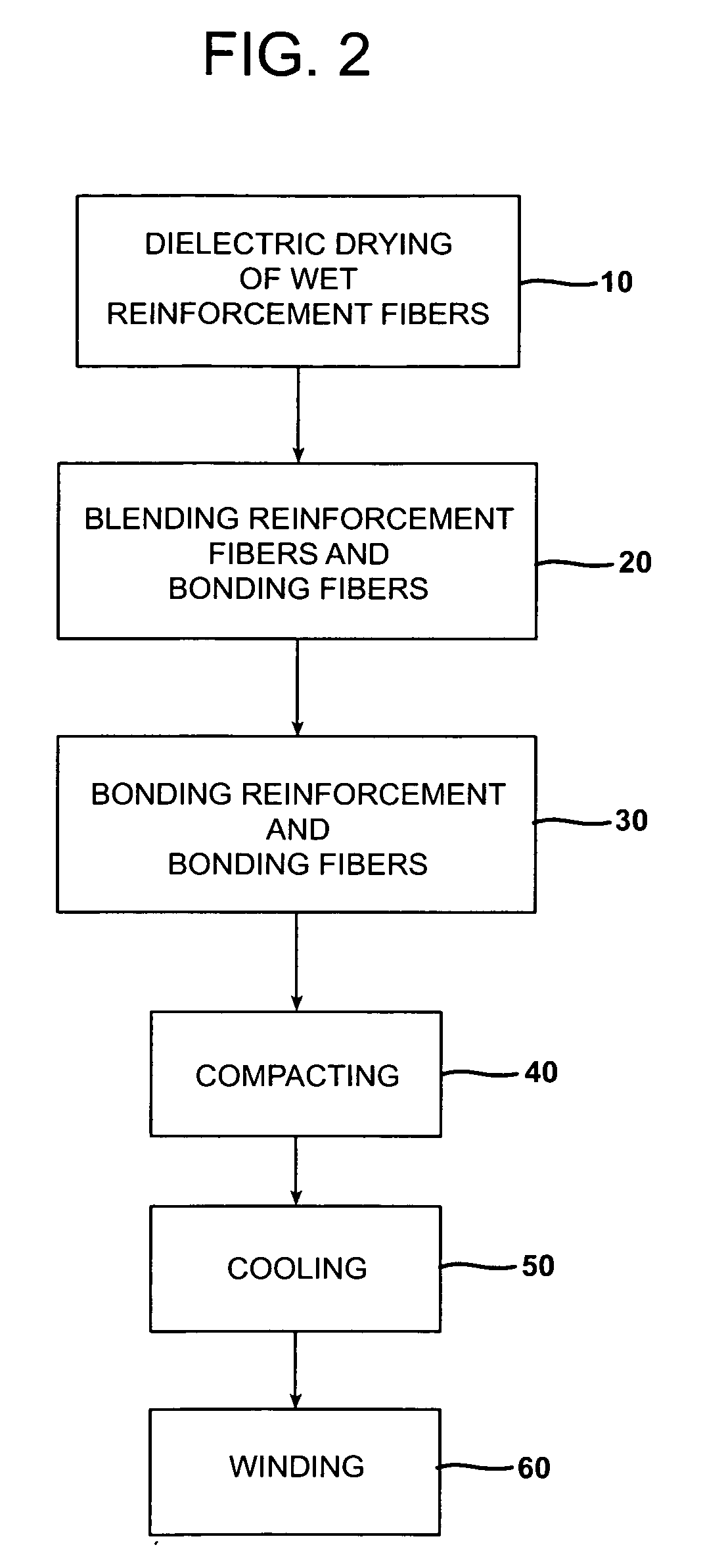
A chopped strand mat formed of bundles of dielectrically dried reinforcing fibers and bonding fibers is provided. The reinforcing fibers may be formed as bundles of wet reinforcing fibers with a bundle tex of about 10 to about 500. The reinforcing fibers may be formed of a single chop length of about 1 to about 1½ inches or a multi-chop length of fibers of about ½ to about 2 inches. The bonding materials may be any thermoplastic or thermosetting material having a melting point less than the reinforcing fiber. The chopped strand mat may be formed by dielectrically drying the wet reinforcement fibers, blending the reinforcement and bonding fibers, bonding the reinforcement and bonding fibers to form a chopped strand mat, compacting the mat, cooling the mat, and winding the mat into a continuous roll. The chopped strand mat contains a uniform or nearly uniform distribution of bonding fibers and bundles of dried reinforcement fibers.

Description

TECHNICAL FIELD AND INDUSTRIAL APPLICABILITY OF THE INVENTION [0001] The present invention relates generally to reinforced composite products, and more particularly, to a chopped strand mat that is formed of bundles of dielectrically dried reinforcing fibers and bonding materials. A method of forming the chopped strand mat is also provided. BACKGROUND OF THE INVENTION [0002] Glass fibers are useful in a variety of technologies. For example, glass fibers are commonly used as reinforcements in polymer matrices to form glass fiber reinforced plastics or composites. Glass fibers have been used in the form of continuous or chopped filaments, strands, rovings, woven fabrics, non-woven fabrics, meshes, and scrims to reinforce polymers. It is known in the art that glass fiber reinforced polymer composites possess higher mechanical properties compared to unreinforced polymers. Thus, better dimensional stability, tensile strength and modulus, flexural strength and modulus, impact resistance, ...

Claims


Application Information

Patent Timeline
IPC IPC(8): B32B27/04B32B27/32B28B3/00
CPCB29C70/12D04H13/007D04H13/002D04H1/42D04H1/4209D04H1/732Y10T428/249942Y10T428/24994Y10T442/643D04H1/43828D04H1/43835D04H1/5416D04H1/43832D04H1/5412D04H1/5418D04H1/5414D04H1/4383D04H1/542D04H1/60B29B11/16
Inventor STRAIT, MICHAEL A.
Owner OCV INTELLECTUAL CAPITAL LLC
Learn More