Vehicle drive control apparatus, vehicle drive control method and program therefor

Inactive Publication Date: 2005-11-22
AISIN AW CO LTD
View PDF11 Cites 53 Cited by
  • Summary
  • Abstract
  • Description
  • Claims
  • Application Information

AI Technical Summary

Benefits of technology

[0010]In the conventional vehicle drive control unit, although the sampling cycle differs depending on each storage item, frames for recording the storage data for all the storage items are formed. Thus, a region for recording the storage data is reserved in the frames, even though there is no need to record the storage data since certain timings do not accord with the storage timing. Thus, the recording capacity of the recording portion constituted by the ring buffer is expanded by that amount. Thus, the cost of the vehicle drive control unit is increased.
[0011]Further, because the ring buffer is provided in the same region as a region used for regular control processing of the RAM, the recording capacity of the region used for the regular control processing is decreased as the recording capacity of the ring buffer is increased.
[0012]The invention thus addresses the above-described problems of the conventional vehicle drive control apparatus. The invention thus provides a vehicle drive control apparatus, a vehicle drive control method and a program thereof, that allows a recording capacity of a recording portion for recording data, which is necessary for determining a cause of an abnormality that has occurred, to be reduced. Accordingly, the cost of the vehicle drive control apparatus can be reduced.
[0016]As a result, a buffer is set for each storage item, storage data of each storage item is recorded in each of the buffers and a frame is formed for each storage item. Thus, even if the sampling cycle differs depending on each of the storage items, the recording capacity of the recording portion constituted by the buffers can be reduced. As a result, the cost of the vehicle drive control apparatus can be lowered.
[0017]Further, it is possible to reduce the recording capacity of the buffers. It is thus possible to increase the recording capacity of the region used for regular control processing by an equivalent amount.
[0018]In addition, a sufficient amount of the storage data can be recorded in the buffers in the recording portion having a predetermined recording capacity. Accordingly, if an abnormality occurs, the cause of that abnormality can be determined accurately.

Problems solved by technology

Thus, the cost of the vehicle drive control unit is increased.

Method used


Image

  • Vehicle drive control apparatus, vehicle drive control method and program therefor
  • Vehicle drive control apparatus, vehicle drive control method and program therefor
  • Vehicle drive control apparatus, vehicle drive control method and program therefor

Examples


Embodiment Construction

[0032]Hereinafter, the preferred embodiment of the invention will be described in detail with reference to the accompanying drawings. In this case, an example in which the invention is applied to a vehicle, for example, a hybrid vehicle as an electric vehicle, will be described.

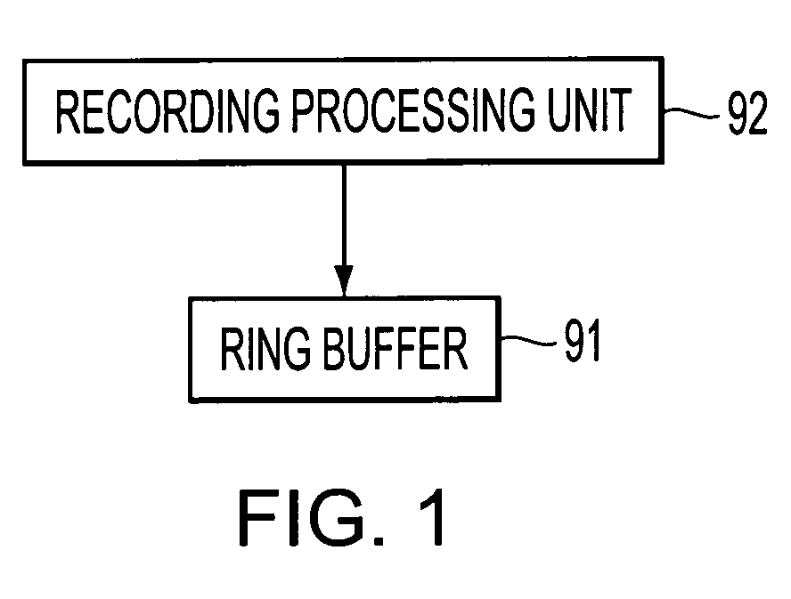
[0033]FIG. 1 is a functional block diagram of a vehicle drive control unit according to the embodiment of the invention. In this figure, reference numeral 91 denotes a ring buffer, as a buffer, which is set for each of a plurality of multiple storage items having different sampling cycles and which constitutes a recording section. Reference numeral 92 denotes a recording processing unit which samples a change amount that changes along with the running of the vehicle, at a sampling cycle set for each of the storage items, and which records that change amount in each buffer as the storage data.

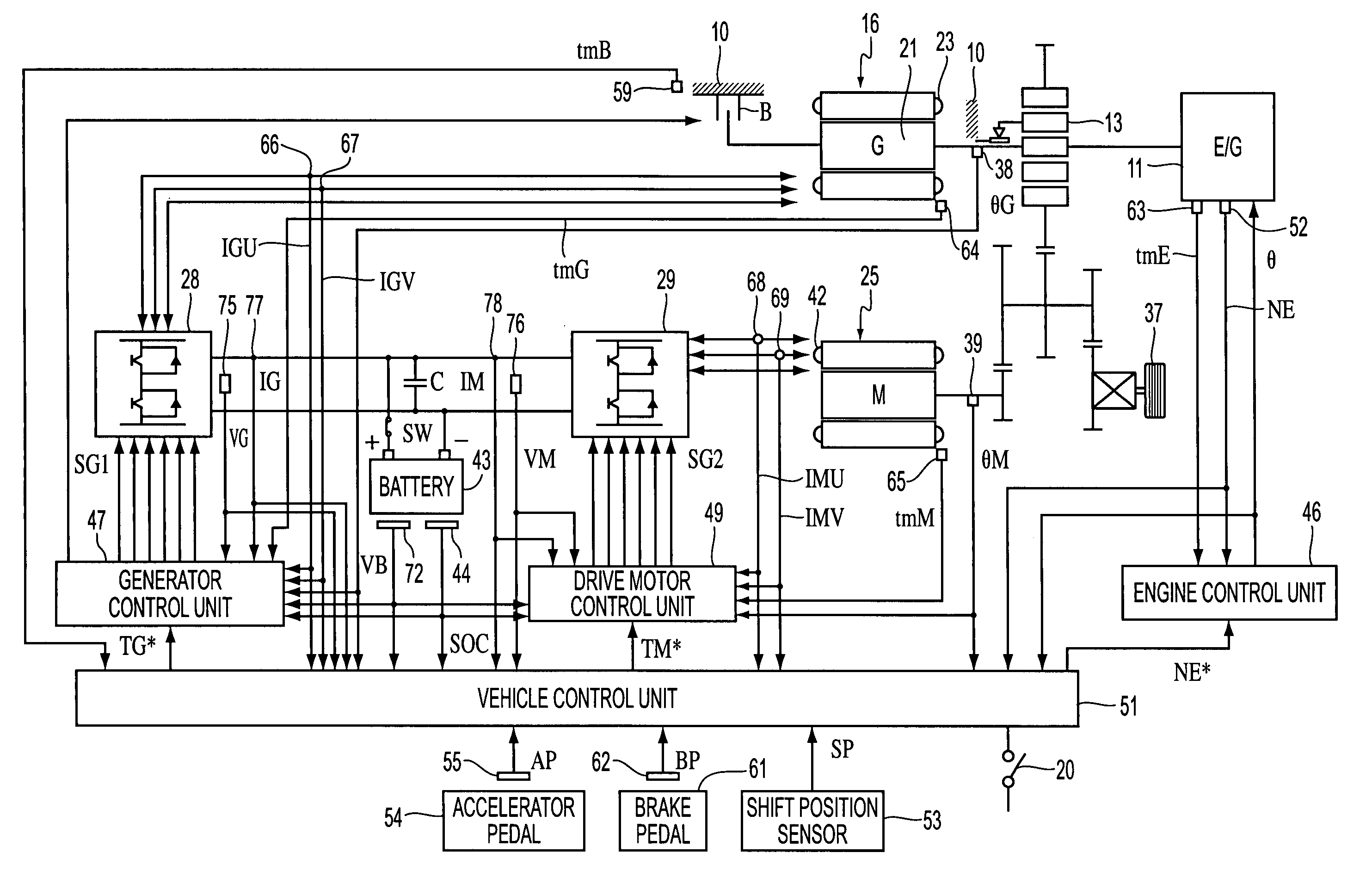
[0034]FIG. 2 is a conceptual diagram of the hybrid vehicle according to the embodiment of the invention. Referring to t...


PUM


Abstract

A vehicle drive control apparatus includes buffers, as a recording portion, set for each of a plurality of storage items, each of the plurality of storage items having a different sampling cycle, and a controller that samples variable quantities, that indicate a status of a vehicle that changes with a running of the vehicle, at a sampling cycle set for each of the plurality of storage items and records the variable quantities in each of the buffers as storage data.

Description

INCORPORATION BY REFERENCE[0001]The disclosure of Japanese Patent Application No. 2002-367614 filed on Dec. 19, 2002 including the specification, drawings and abstract is incorporated herein by reference in its entirety.BACKGROUND OF THE INVENTION[0002]1. Field of Invention[0003]The invention relates to a vehicle drive control apparatus, a vehicle drive control method and a program thereof.[0004]2. Description of Related Art[0005]Conventionally, a vehicle drive apparatus is loaded on a vehicle, for example, an electric vehicle. A drive motor, as an electric motor device, generates drive motor torque that is transmitted to drive wheels. The drive motor is powered (driven) by receiving direct current from a battery at the time of driving the wheels so as to generate the drive motor torque. During regeneration (generation), torque resulting from the inertia of the electric vehicle is received to generate a direct current and this generated direct current is supplied to the battery.[000...

Claims


Application Information

Patent Timeline
IPC IPC(8): B60K6/04B60K6/00G07C5/00G07C5/08B60K6/445B60L50/16B60W20/00G05B23/02
CPCG07C5/085B60W20/00G05B23/00B60W20/50
Inventor OKADA, RIETOMIYA, NORIOIZAWA, KAZUYUKI
Owner AISIN AW CO LTD
Why Eureka
Try Eureka