
Electronic package of photo-image sensors in cellular phone camera modules, and the fabrication and assembly thereof

Active Publication Date: 2005-04-07
OPTOPAC
View PDF10 Cites 43 Cited by
  • Summary
  • Abstract
  • Description
  • Claims
  • Application Information

AI Technical Summary

Benefits of technology

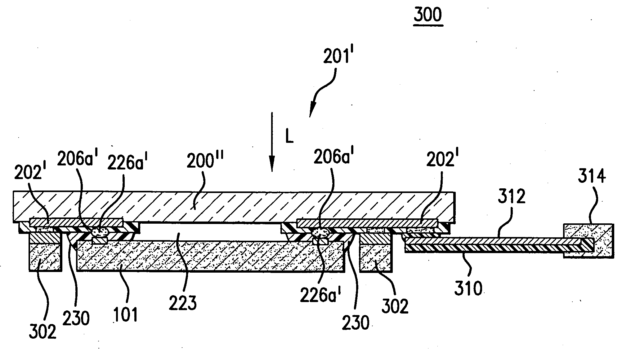
[0022] Also, the substrate includes at least one patterned passivation layer over the patterned metal layer for protecting the interconnection lines formed thereby. This patterned passivation layer has openings at the solder wetable pads.
[0027] The module is highly minimized in size to chip scale levels by, among other things, eliminating at least some of the solder joints outside and about the module's photo-image sensor die. The resulting electronic module may provide a lower cost solution by eliminating the need for a PCB which is necessary in COB modules.

Problems solved by technology

Unfortunately, none of these packaged photo-sensor image types are, in practice, viable alternatives for cellular phone camera module applications because of the resulting module's excessive size.
Perhaps the most critical drawback with this package is the complexity both in structure and fabrication process.
This complexity is a significant factor in mass production since complexity tends to increase the processing yield loss.
As a result of its complexity and attendant yield loss, the package is expensive to fabricate.
Other nontrivial disadvantages of this technique include its need for a wide dicing line, which cuts against the trend in semiconductor manufacturing to decrease the width of dicing lines to achieve more dice per wafer.
The current typical dicing line width of about 100 micrometers is not wide enough to support this technique.
Consequently, the packaging technique is not compatible with semiconductor wafers having standard dicing line widths, and requires customizing measures to ensure the wider than usual dicing line widths.

Method used


Image

  • Electronic package of photo-image sensors in cellular phone camera modules, and the fabrication and assembly thereof
  • Electronic package of photo-image sensors in cellular phone camera modules, and the fabrication and assembly thereof
  • Electronic package of photo-image sensors in cellular phone camera modules, and the fabrication and assembly thereof

Examples


Embodiment Construction

[0047] A photo-sensing semiconductor wafer has a plurality of dice, and each die has integrated circuitry formed on a front surface of the wafer, much as in other semiconductor wafers. Each die has a plurality of bonding pads. The wafer has a patterned passivation layer over the front surface for protecting the integrated circuitry underneath. The passivation layer has openings on said bonding pads. Each such photo-sensing die has at least one photo-sensing area on a front surface.

[0048] Wafer bumping is a well-known technique that has been widely used since its initial teaching, as reflected in U.S. Pat. No. 3,292,240 entitled “Method of Fabricating Microminiature Functional Components,” assigned to IBM. A typical wafer bumping process includes at least one patterned metal layer for making solder bump pads connected to bonding pads on the wafer. Metallurgy used for solder bump pads is commonly referred to as under bump metallurgy (UBM) and typically utilizes a multilayered structu...


PUM


Abstract

A photo-sensing device package and the method of packaging such device is provided. The package includes an assembly portion having a substrate formed of a material substantially transparent to light within a predetermined range of wavelengths and a sensing portion having at least one photo-sensing die photo-electronically transducing light within the predetermined range of wavelengths. The assembly portion is formed with at least one metal layer disposed on the substrate about a front surface region thereof, and at least one passivation layer formed to extend over the metal layer. The passivation layer is patterned to define a plurality of first and second access openings respectively about a plurality of first solder wettable pads and at least one second solder wettable pad on the metal layer. Each of the first solder wettable pads is joined by a first solder joint to a solder bump pad formed on the sensing portion, while the second solder wettable pad is joined by a second solder joint to external circuitry.

Description

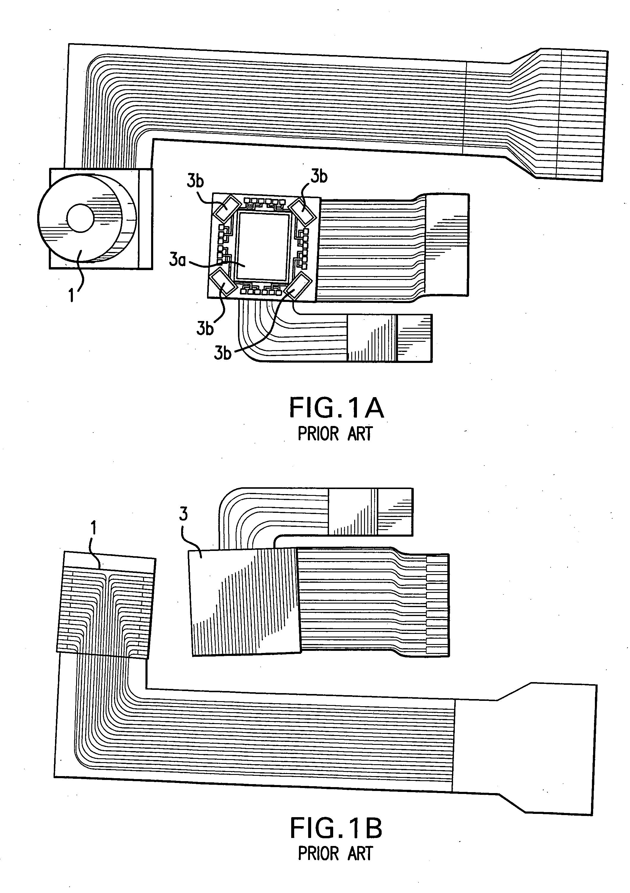
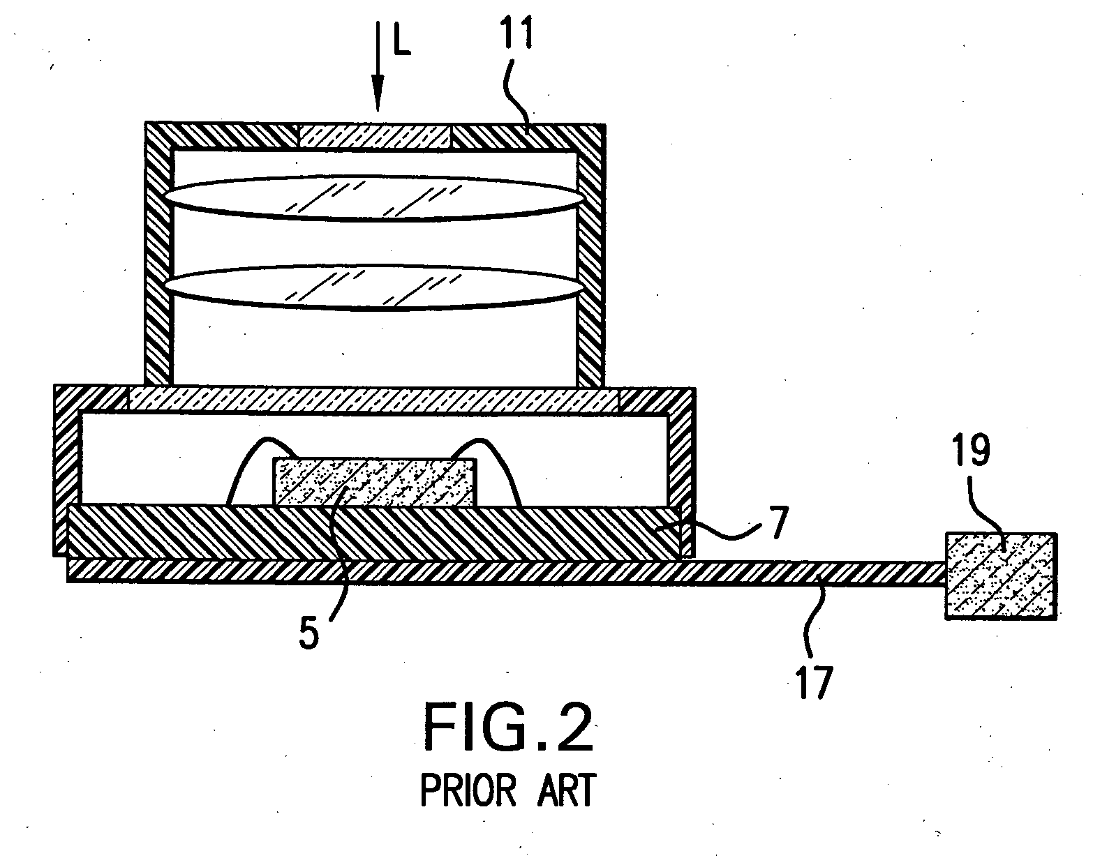
RELATED U.S. APPLICATION DATA [0001] This Application is based on U.S. Provisional Patent Application Ser. No. 60 / 536,536, filed 15 Jan. 2004. This Application is a Continuation-In-Part of co-pending U.S. Non-provisional patent application Ser. No. 10 / 692,816, filed 23 Oct. 2003, which is based on U.S. Provisional Patent Application Ser. No. 60 / 507,100, filed 1 Oct. 2003.BACKGROUND OF THE INVENTION [0002] 1. Field of the Invention [0003] The present invention relates generally to electronic packaging of semiconductor integrated circuits, and particularly, to electronic packaging of photo-sensing semiconductor devices. More specifically, the present invention relates to electronic packaging of photo image sensors in such compact applications as cellular telephone camera modules. [0004] 2. Prior Art [0005]FIGS. 1A, 1B illustrate top and bottom views of typical camera modules 1, 3 often employed in cellular telephones. In the smaller of the modules 3, the lens housing is removed to mor...

Claims


Application Information

Patent Timeline
IPC IPC(8): H01L21/00H01L21/50H01L23/52H01L27/14H01L27/146H01L29/40H01L31/0203
CPCH01L27/14618H01L27/14625H01L2224/45144H01L2924/01322H01L2924/19041H01L27/14645H01L27/14683H01L2224/48091H01L2224/48227H01L2924/01077H01L2924/01078H01L2924/01079H01L2924/15787H01L2924/16195H01L2924/00014H01L2924/00H01L2924/16151H04N23/57H01L27/14H01L23/50
Inventor KIM, DEOK-HOON
Owner OPTOPAC
Learn More