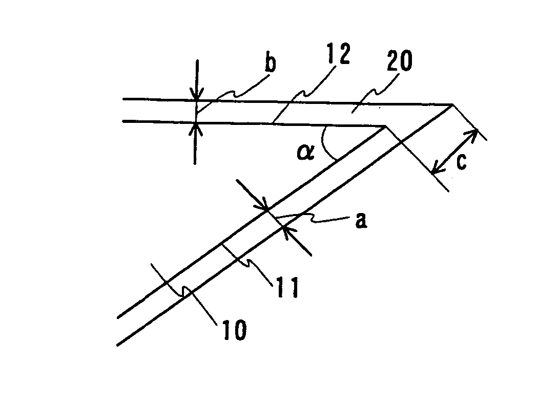
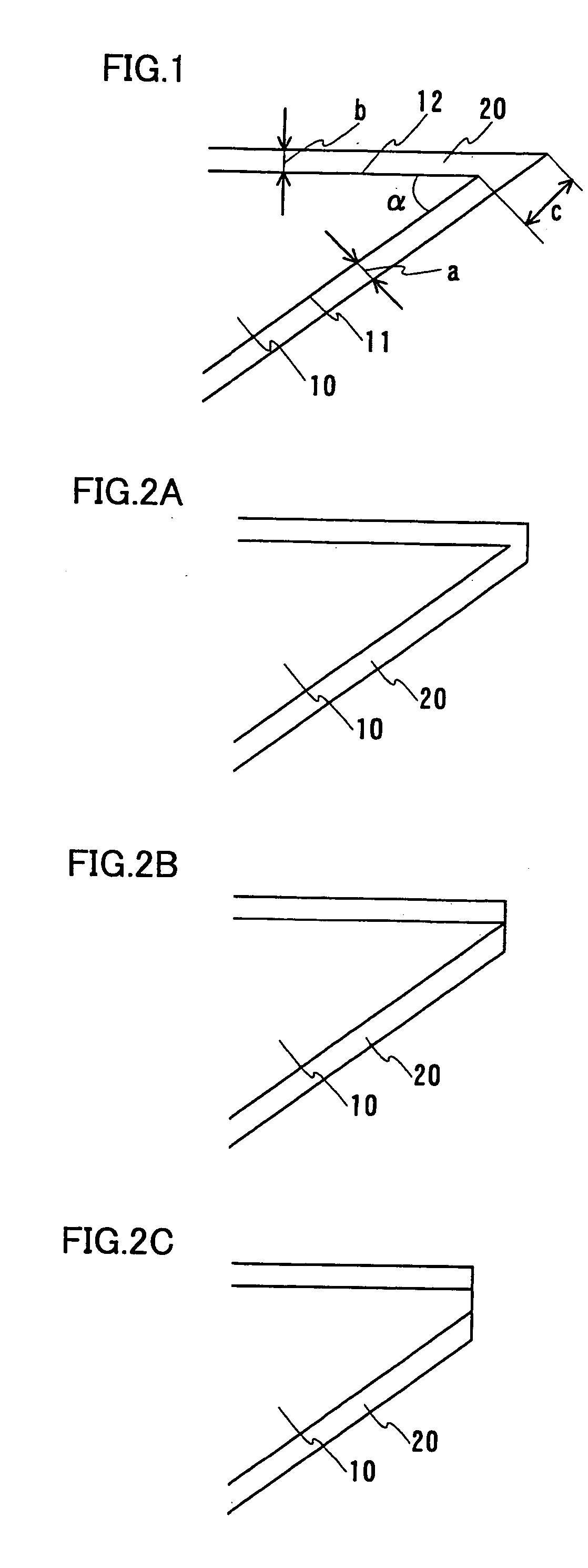
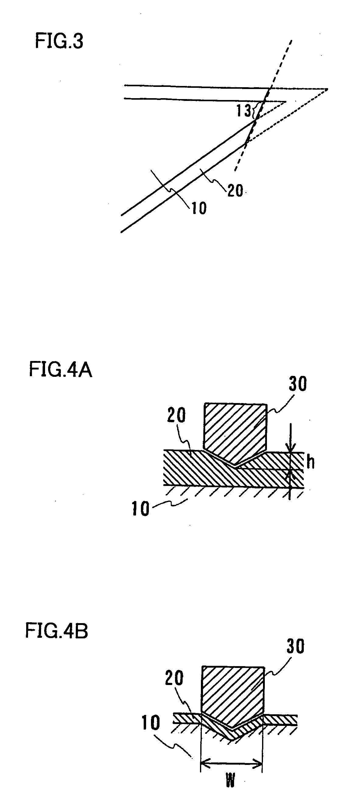
Surface-coated cutting tool
a cutting tool and surface coating technology, applied in the field of cutting tools, can solve the problems of increasing the cutting edge temperature of the cutting tool, increasing the characteristics required of the tool material, etc., and achieves the effects of excellent fracture resistance, high hardness, and excellent chipping resistan
- Summary
- Abstract
- Description
- Claims
- Application Information
AI Technical Summary
Benefits of technology
Problems solved by technology
Method used
Image
Examples
example 1
[0088] The following surface-coated cutting tools were prepared for investigation of wear resistance.
[0089] (1) Preparation of Sample
[0090] Each base prepared from cemented carbide of grade P30 under JIS having an insert shape SPGN120308 under JIS was mounted on a base holder of a well-known cathode arc ion plating apparatus. As the base holder, that allowing water cooling was employed. First, the internal pressure of a chamber was reduced and the insert-shaped base was heated to a temperature of 650° C. with a heater set in the apparatus while rotating the base holder, and the chamber was evacuated until the internal pressure reached 1.0×10⁻⁴ Pa. Then, argon gas was introduced into the chamber for holding the internal pressure of the chamber at 3.0 Pa, and the voltage of a base bias power source was gradually increased up to 1500 V, for cleaning the base surface for 15 minutes. Then, the argon gas was discharged from the chamber.
example 2
[0100] Drills comprising coating films were obtained by preparing a plurality of bases of drills (cemented carbide K10 under JIS) having outer diameters of 8 mm and forming coating films on the bases respectively. The coating films were provided similarly to those of the samples 2, 11, 16, 19, 32, 51 and 52 in the aforementioned Example 1. These drills comprising the coating films were employed for drilling SCM440 (HRC30), and the tool lives were evaluated.
[0101] The cutting conditions were a cutting speed of 90 m / min. a feed rate of 0.2 mm / rev., employment of no coolant (using air blow) and blind hole cutting of 24 mm in depth. The tool life of each sample was determined when the dimensional accuracy of a workpiece was out of a defined range and evaluated with the number of holes formed before the end of the life. Table 5 shows the results.
TABLE 5SampleSampleSampleSampleSampleSampleSample2-22-112-162-192-322-512-52Film TypeWorkingSampleSampleSampleSampleSampleSampleSampleContent...
example 3
[0103] End mills comprising coating films were obtained by preparing a plurality of bases of six-flute end mills (cemented carbide K10 under JIS) having outer diameters of 8 mm and coating films were formed on the bases respectively by a method similar to that in Example 1. The coating films were prepared similarly to those of the samples 2, 11, 16, 19, 32, 51 and 52 in the aforementioned Example 1. These end mills comprising the coating films were employed for end mill side cutting of SKD 11 (HRC60), and the tool lives were evaluated.
[0104] The cutting conditions were a cutting speed of 200 m / min., a feed rate of 0.03 mm / edge, a depth of cut Ad of 12 mm, Rd of 0.2 mm and employment of no coolant (using air blow). The tool life of each sample was determined when the dimensional accuracy of a workpiece was out of a defined range and evaluated with the cutting length before the end of the life. Table 6 shows the results.
TABLE 6SampleSampleSampleSampleSampleSampleSample3-23-113-163-...
PUM
| Property | Measurement | Unit |
|---|---|---|
| thickness | aaaaa | aaaaa |
| thickness | aaaaa | aaaaa |
| thickness | aaaaa | aaaaa |
Abstract
Description
Claims
Application Information
 - R&D
- Intellectual Property
- Life Sciences
- Materials
- Tech Scout
- Unparalleled Data Quality
- Higher Quality Content
- 60% Fewer Hallucinations
Browse by: Latest US Patents, China's latest patents, Technical Efficacy Thesaurus, Application Domain, Technology Topic, Popular Technical Reports.
© 2025 PatSnap. All rights reserved.Legal|Privacy policy|Modern Slavery Act Transparency Statement|Sitemap|About US| Contact US: help@patsnap.com


