
Evaluating the urethra and the periurethral Tissues

a urethral tissue and periurethral tissue technology, applied in the field of in vivo mri, can solve the problems of coagulation necrosis of the tissue, patients treated with cryosurgery are at risk of developing impotence and incontinence after treatment, and advanced carcinoma, by contrast, is not appropriately treated using any of these regimens, so as to reduce the potential rf heating effect and improve coil performan

Inactive Publication Date: 2006-06-08
SURGIVISION
View PDF99 Cites 26 Cited by
  • Summary
  • Abstract
  • Description
  • Claims
  • Application Information

AI Technical Summary

Benefits of technology

This system enables ultra-high resolution MR images of the female urethra and accurate evaluation of the male prostate, providing improved diagnostic capabilities and potential therapeutic guidance for urinary incontinence and prostate conditions.

Problems solved by technology

The cycle of freezing and thawing of the prostate tissue results in coagulation necrosis of the tissue.
As with other forms of therapy, patients treated with cryosurgery are at risk of developing impotence and incontinence after treatment.
Advanced carcinoma, by contrast, is not appropriately treated using any of these regimens.
In addition to the significant psychosocial burden borne by individuals with this ailment, incontinence involves quantifiable health care and related costs, conservatively estimated at approximately $10 billion annually.
In many cases, urinary incontinence is a chronic problem, lasting indefinitely unless properly diagnosed and treated.
In part, this is due to inadequate knowledge about the anatomical basis, pathophysiology and potential treatments for the condition.
Despite these efforts, clinical and radiological evaluation of these areas remains difficult and not completely satisfying.
Although high-resolution magnetic resonance imaging with phased array pelvic, endorectal and endovaginal coils has dramatically enhanced the ability to visualize abnormalities of the female urethral and periurethral tissues, discussion and controversy still continues about the anatomy of this region.
Repair of cloacal extrophy is challenging for it requires staged reconstruction of the pelvic urinary structures as well as the gastrointestinal tract.
Mutual inductance between two or more independent but geometrically adjacent coils, tuned to the same resonance frequency may under certain circumstances improve the SNR and signal homogeneity, but such designs can also result in coupling between the coils that might result in poor signal performance and decreased signal penetration depth into the tissue.
Geometric decoupling, however, does not always result in sufficient isolation.
The overall coil performance might be still degraded due to residual coupling between the coils.
However, there has been no simple method of eliminating coupling between elements of these types of designs taught, thereby impeding the clinical uses of such devices.

Method used


Image

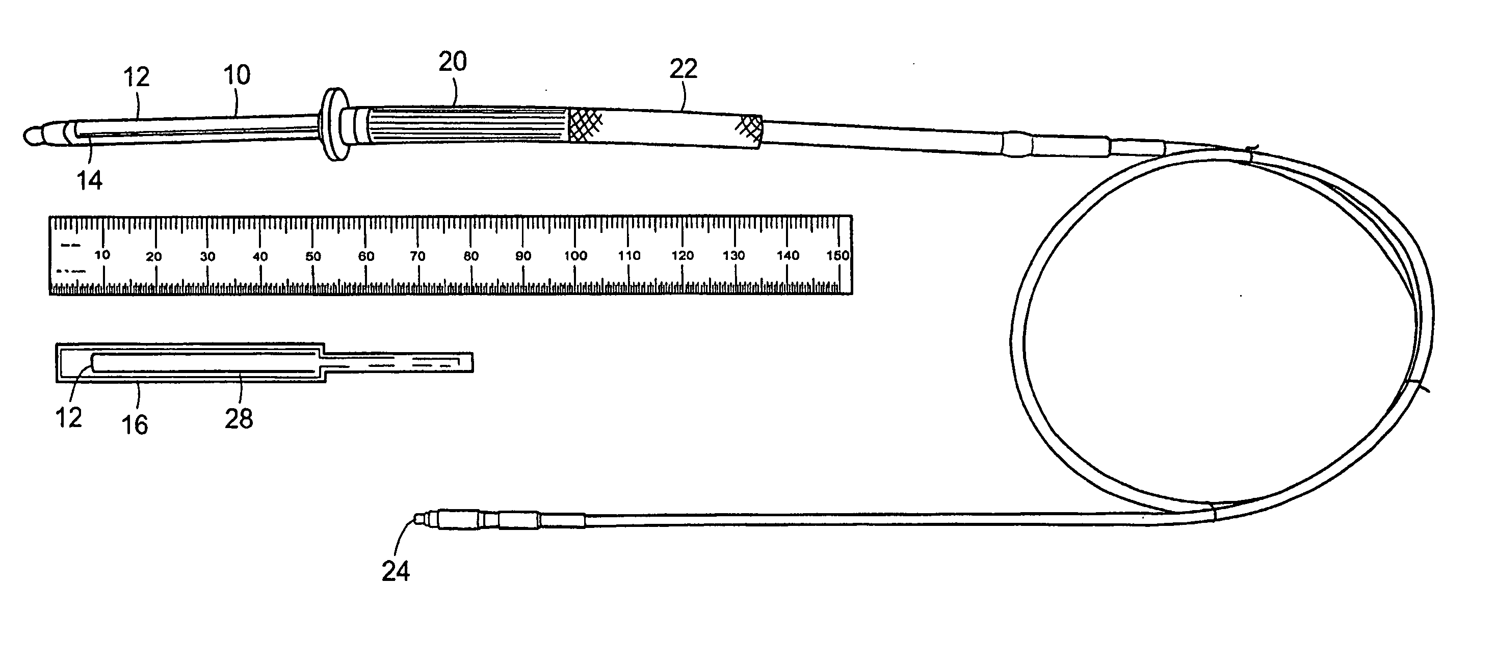
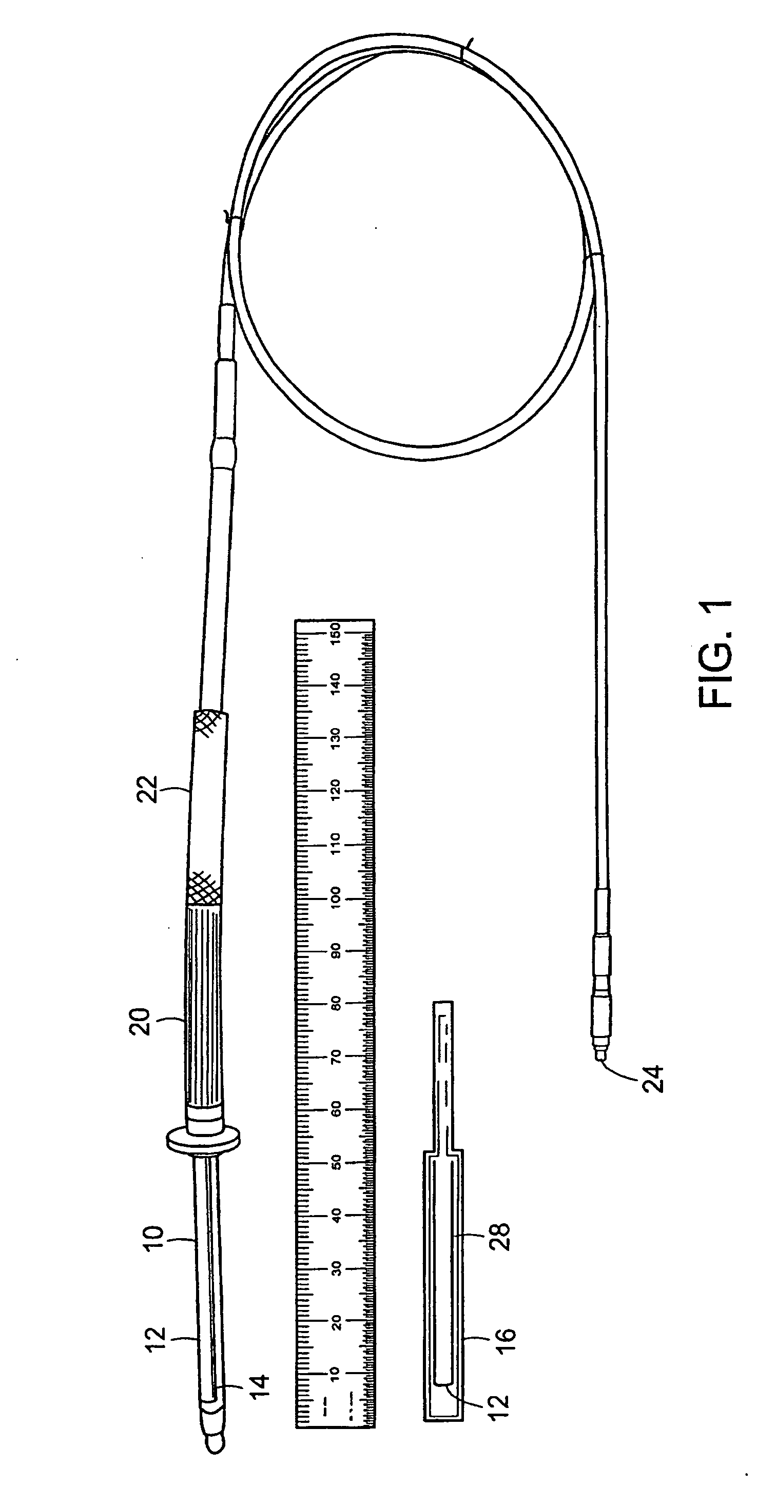
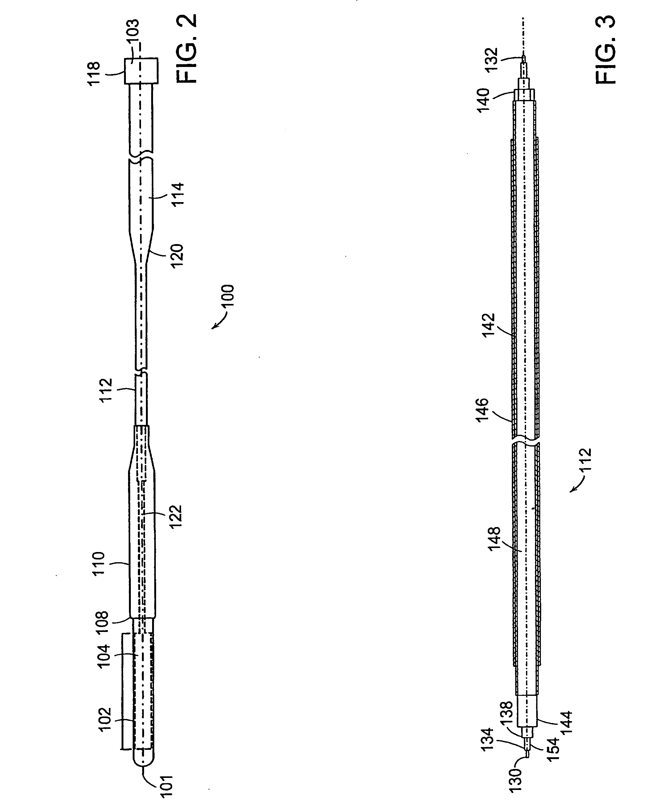
  • Evaluating the urethra and the periurethral Tissues
  • Evaluating the urethra and the periurethral Tissues
  • Evaluating the urethra and the periurethral Tissues

Examples


example 1

Heating Properties

[0088] Heating experiments were performed with the coil inserted into agar gel (DIFCO Laboratories, Franklin Lakes, N.J.) phantom doped with 0.45% NaCl to mimic the electrical properties of the body. The conductivity of the gel was measured to be 0.8 S / m at 64 MHz, a median value in the range of human tissues. Temperature was monitored with an eight-channel fluoroptic thermometer (UMI 8, FISO Technologies, Inc., Quebec, Canada). Five sensors were equally spaced and placed adherent to the outer coil tubing along one conductor of the single-loop coil. Thus, two sensors had direct contact with the distal and proximal edge of the flexible circuit. A sixth sensor was placed at the opening of the balun circuit.

[0089] The specific absorption rate (SAR) was calculated by finding the initial slope of the temperature rise (dT / dt) and multiplying by the specific heat capacity of the agar gel, C=4180 J / kg. Scanning was performed on a 1.5T Signa LX(GE Medical Systems, Milwauk...

example 2

In Vitro Testing

[0091] Imaging was performed using the body coil of the scanner as RF transmitter and the endourethral coils as receive-only probes. For assessing the signal characteristics of the antennas, proton density (PD)-weighted axial and coronal images were acquired with a fast spin-echo (FSE) sequence (PD-FSE: 8 echoes, TR / TE=2000 / 14.5 ms, BW=15.6 kHz, 6 NEX). Axial 3 min sections with a 30×30 min field of view (FOV) and a 256×128 matrix as well as coronal 2 min sections with a 80×80 min FOV and a 256×128 matrix were collected in 3:24 min.

[0092] The coils' imaging performance was evaluated in one formalin fixated as well as in six freshly harvested female human cadaver pelvices. The coils were subsequently introduced into the urethra with the tip entering the bladder by approximately 5 mm. This position ensured the whole urethra and the internal sphincter to be covered by highest signal intensity and homogeneity of the coil. For localization purposes, a 5″×9″ rectangular ...

examples 1 and 2

Results of Examples 1 and 2

[0094] For each position of the coil / phantom in the scanner, the temperature increases from sensor 1 to sensor 5, i.e. from the inside of the phantom to the edge of the phantom (Table 1).

TABLE 1SAR rise within 10:00 min of scanning at five different locations along thecoil. The imaging region of the coil as well as the mouth of the coaxial chokewere inserted into agar-gel by approximately 75 mm. Positions of the coil / phantomin the scanner were: a) middle of bore, coil connected, b) middle of bore,coil disconnected, i.e. decoupling disabled, c) close to scanner bore, coilconnected, and d) close to scanner bore, decoupling disabled.SARSARSARSARSARSARPosition[W / kg][W / kg][W / kg][W / kg][W / kg][W / kg]of coilSensor 1Sensor 2Sensor 3Sensor 4Sensor 5Sensor 6a)0.630.671.051.261.681.54b)1.121.121.751.681.821.70c)1.681.41.822.312.452.07d)3.783.784.345.045.324.32

[0095] The temperature increases when the coil is disconnected from the scanner surface coil port, i.e. when t...


PUM


Abstract

Systems and methods for the evaluation of the urethra and periurethral tissues may involve an MRI coil adapted for insertion into the male, female or pediatric urethra. The MRI coil may be in electrical communication with an interface circuit made up of a tuning-matching circuit, a decoupling circuit and a balun circuit. The interface circuit may also be in electrical communication with a MRI machine. In certain practices, the present invention provides methods for the diagnosis and treatment of conditions involving the urethra and periurethral tissues, including disorders of the female pelvic floor, conditions of the prostate and anomalies of the pediatric pelvis.

Description

CROSS-REFERENCE TO RELATED APPLICATIONS [0001] This application is a division of U.S. patent application Ser. No. 09 / 824,536, filed Apr. 2, 2001, now U.S. Pat. No. 6,898,454, which claims the benefit of U.S. Provisional Patent Application No. 60 / 194,060 filed Mar. 31, 2000, and which is a continuation-in-part of U.S. patent application Ser. Nos. 09 / 536,090 filed Mar. 24, 2000, now U.S. Pat. No. 6,675,033 and 09 / 549,921 filed Apr. 14, 2000, now U.S. Pat. No. 6,549,800, which itself is a continuation-in-part of U.S. patent application Ser. No. 09 / 360,144, filed Jul. 26, 1999, now abandoned, which is a continuation-in-part of U.S. patent application Ser. No. 08 / 638,934, filed Apr. 25, 1996, now U.S. Pat. No. 5,928,145. U.S. patent application Ser. No. 09 / 824,536 is also a continuation-in-part of U.S. Patent Application Ser. Nos. 09 / 191,563 filed Nov. 13, 1998, now U.S. Pat. No. 6,263,229, and 09 / 817,893 filed Mar. 26, 2001, now U.S. Pat. No. 6,628,980. The entire disclosures of each of...

Claims


Application Information

Patent Timeline
Patent Type & Authority Applications(United States)
IPC IPC(8): A61B5/05A61B1/273A61B1/303A61B1/307A61B1/31A61B5/055G01R33/28G01R33/34H01Q1/36H01Q1/40H01Q1/44H01Q11/08
CPCA61B1/273A61B1/303A61B1/307A61B1/31A61B5/055A61B5/415A61B5/418A61B5/4381G01R33/285G01R33/34007G01R33/34084G01R33/341H01Q1/36H01Q1/362H01Q1/40H01Q1/44H01Q11/08
Inventor ATALAR, ERGINQUICK, HARALD HARTMUTKARMARKAR, PARAG
Owner SURGIVISION
Learn More