
Method of making a protective coating forming a thermal barrier with a bonding underlayer on a superalloy substrate, and a part obtained thereby

a technology of superalloy and thermal barrier, which is applied in the direction of chemical vapor deposition coating, machine/engine, record information storage, etc., can solve the problems of easy weight penalty and difficult control of the precise composition of the bonding underlayer, and achieve the effect of small thickness

Inactive Publication Date: 2004-02-12
SN DETUDE & DE CONSTR DE MOTEURS DAVIATION S N E C M A
View PDF6 Cites 10 Cited by
  • Summary
  • Abstract
  • Description
  • Claims
  • Application Information

AI Technical Summary

Benefits of technology

The solution achieves a bonding underlayer with a thickness less than 50 μm, free from substrate diffusion, and forms a persistent, adhesive alumina film for a ceramic outer layer, enhancing thermal stability and mechanical properties of gas turbine parts without weight penalties.

Problems solved by technology

Nevertheless, in order to obtain a thermally-stable underlayer, it is necessary for it to be relatively thick, typically not less than 50 micrometers (.mu.m) to 100 .mu.m, and that gives rise to a weight penalty.
The Applicant has observed that various elements of the superalloy substrate diffusing into the bonding underlayer can form undesirable precipitates therein that are liable in particular to affect the alumina film developed on the surface of the bonding underlayer.
In addition, it is difficult to control the precise composition of the bonding underlayer.

Method used


Image

  • Method of making a protective coating forming a thermal barrier with a bonding underlayer on a superalloy substrate, and a part obtained thereby
  • Method of making a protective coating forming a thermal barrier with a bonding underlayer on a superalloy substrate, and a part obtained thereby
  • Method of making a protective coating forming a thermal barrier with a bonding underlayer on a superalloy substrate, and a part obtained thereby

Examples


example 1

[0075] A nickel-based superalloy metal substrate for a high pressure turbine blade of a turbojet engine was provided with a bonding underlayer made of an intermetallic compound, as follows:

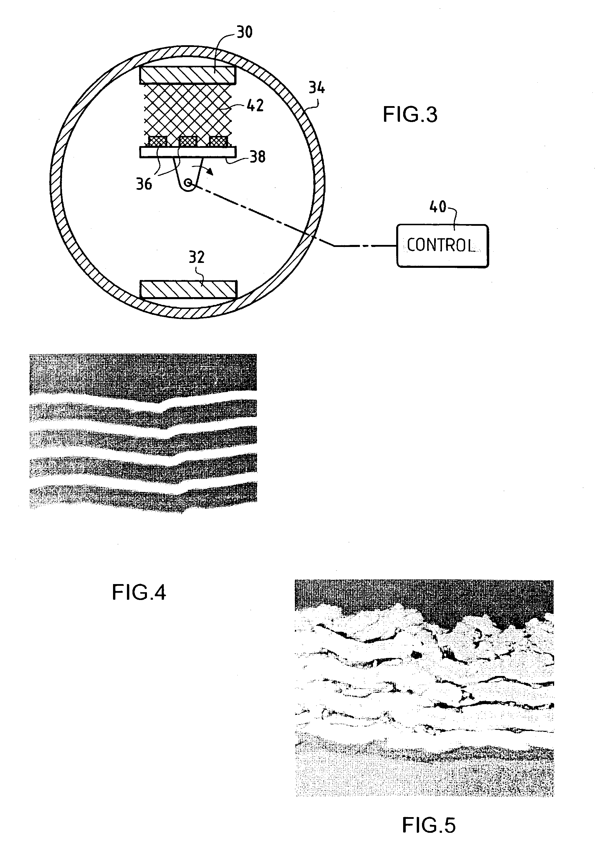
[0076] Five individual layers of platinum each having a thickness of about 500 nm were deposited in alternation with four individual layers of aluminum each having a thickness of about 1330 nm. The individual layers were formed by cathode sputtering under the conditions described with reference to FIG. 3.

[0077] FIG. 4 shows the individual platinum layers (pale color) and the individual aluminum layers (dark color) as obtained after deposition.

[0078] Heat treatment was then performed in an inert atmosphere (argon) at a temperature of 700.degree. C. for a period of 2 h. A bonding underlayer having a total thickness equal to about 7.8 .mu.m was obtained and it comprised an intermetallic compound of the PtAl.sub.2 type.

[0079] FIG. 5 is a section through the structure of the bonding underlayer. It can ...

example 2 (

FOR COMPARISON)

[0082] A bonding underlayer having substantially the same total thickness and the same composition as that of Example 1 was formed on a substrate of the same kind as that used in Example 1 and under analogous conditions, except that it was made by depositing three individual layers of platinum each having a thickness of 833 nm in alternation with two individual layers of aluminum each having a thickness of 2650 nm. Adhesion testing performed under the same conditions as in Example 1 revealed poor adhesion to the substrate. In addition, the outer surface of the underlayer presented defects (depressions) revealing localized melting of the aluminum.

example 3

[0083] A nickel-based superalloy metal substrate for a high pressure turbine blade of a turbojet engine was provided with an intermetallic thermal barrier underlayer as follows:

[0084] Two individual layers of platinum each having a thickness equal to about 1150 nm were deposited on the substrate together with an intermediate layer of aluminum having a thickness of about 1400 nm. The layers were formed by cathode sputtering.

[0085] Heat treatment was then performed in an inert atmosphere (argon) at 700.degree. C. for a period of 2 h. The platinum and aluminum layers then reacted exothermally to form an intermetallic compound Pt.sub.5Al.sub.3. The underlayer having a total thickness of about 3.7 .mu.m retained a laminated structure.

[0086] Analysis performed as in Example 1 showed that the underlayer was made up only of the elements supplied (aluminum and platinum) and did not include any traces of elements from the substrate.


PUM

PropertyMeasurementUnit
temperatureaaaaaaaaaa

Abstract

A protective coating forming a thermal barrier is made on a superalloy metal substrate by forming a bonding underlayer on the substrate, the bonding underlayer being constituted by an intermetallic compound comprising at least aluminum and a metal from the platinum group, and by forming a ceramic outer layer which is anchored on a film of alumina present on the surface of the bonding underlayer. The bonding underlayer preferably has a thickness of less than 50 mum and is made by using physical vapor deposition, e.g. by cathode sputtering, to deposit a plurality of individual layers alternately of aluminum and of a metal from the platinum group, and by causing the metals in the resulting layers to react together exothermally.

Description

[0001] The invention relates to making parts comprising a metal substrate provided with a protective coating forming a thermal barrier.[0002] The field of application of the invention is making parts capable of retaining their mechanical properties at high temperatures, in particular gas turbine parts such as turbine blades, in particular for turbojet engines.[0003] To improve the performance of gas turbines, and in particular the efficiency thereof, it is desirable to run them at temperatures that are as high as possible. To make parts for the hot portions, it is well known to use superalloys. As a general rule, superalloys comprise nickel as the main component and additional elements usually selected from chromium, cobalt, aluminum, molybdenum, titanium, tantalum, and many others.[0004] Operating temperature can be further increased by providing the metal substrate of such parts with a protective coating that constitutes a thermal barrier.[0005] It is known for this purpose to mak...

Claims


Application Information

Patent Timeline
Patent Type & Authority Applications(United States)
IPC IPC(8): F01D5/28C22C5/04C23C14/14C23C14/16C23C14/34C23C28/00F02C7/00
CPCC23C14/165C23C14/3464Y02T50/67C23C28/321C23C28/322C23C28/345Y10T428/12875C23C28/42Y10T428/12944Y10T428/12736Y10T428/12611Y10T428/265C23C28/3455Y02T50/60
Inventor SAINT RAMOND, BERTRANDNICHOLLS, JOHN
Owner SN DETUDE & DE CONSTR DE MOTEURS DAVIATION S N E C M A
Learn More