
Corrosion-resistant metallic member, metallic separator for fuel cell comprising the same, and process for production thereof

a technology of metallic separator and fuel cell, which is applied in the direction of sustainable manufacturing/processing, final product manufacture, electrochemical generators, etc., can solve the problems of poor adhesion to the base, poor corrosion resistance of the plated product thus obtained, and poor corrosion resistance of the deposit, so as to increase the amount of metal ions extracted, the effect of high corrosion resistan

Inactive Publication Date: 2003-04-10
DAIDO STEEL CO LTD
View PDF7 Cites 49 Cited by
  • Summary
  • Abstract
  • Description
  • Claims
  • Application Information

AI Technical Summary

Benefits of technology

[0162] It was ascertained from those results that the corrosion-resistant metallic members 201 of Examples 5 to 11 had high corrosion resistance, high adhesion strength of the thin gold layer 206, and low contact electrical resistance. Furthermore, it can be easily understood that the effects of the invention were demonstrated.
[0163] Corrosion-resistant metallic members 201 of Examples 12 to 24 and Comparative Examples 7 and 8 were obtained in the same manner as in the Examples shown in Table 5, except that gold, palladium, platinum, or an AU--Co alloy was deposited by plating or vapor deposition on a 1 mm-thick metallic base 202 made of a stainless steel (SUS 430, SUS 304, SUS 304L, SUS 316L, or SUS XM7), an Ni--Cr alloy, pure titanium, or pure aluminum. These metallic members are shown in Table 6.
[0164] Test pieces of the two sizes shown above were cut out of each of the corrosion-resistant metallic members 201. The test pieces each were subjected to the corrosion test to determine the amounts of metal ions extracted and to the peeling test to determine the amount of deposit peeled off. The test pieces were further subjected to the contact electrical resistance test. The results obtained are shown in Table 6.
[0165] Table 6 shows the following. In each of Examples 12 to 24, the amounts of ions of metals extracted were small as in the Examples shown in Table 5. The amount of deposit peeled off in all these Examples was 0%, and the contact resistances therein were all 10 m.OMEGA..multidot.cm.sup.2 or less.
[0166] In contrast, in Comparative Example 7, the amounts of metal ions extracted were large, the amount of deposit peeled off was 100%, and the contact resistance was as high as 89.6 m.OMEGA..multidot.cm.sup.2. Such results were obtained because the corrosion-resistant metallic member of Comparative Example 7 had undergone no working after the vapor deposition of a thin gold layer and hence had pinholes and pores therein.
[0167] In Comparative Example 8, the amounts of metal ions extracted were large as in Comparative Example 7 but the amount of deposit peeled off was as small as 0%. The contact resistance therein was as high as about 37.0 m.OMEGA..multidot.cm.sup.2. It was thought that since the corrosion-resistant metallic member of Comparative Example 8 was produced by vapor-depositing a thin gold layer of 5 nm and rolling the gold layer at a draft as high as 90% to reduce the thickness thereof to as small as 0.5 nm, the surface of the metallic base 202 (substrate) was locally exposed and this resulted in the increased contact resistance and the increased amounts of metal ions extracted.

Problems solved by technology

In producing plated products, plating is conducted after the base has been formed into the shape of the final product, because forming after plating may result in peeling of the deposit.
There has hence been a problem that a film is less apt to be deposited by plating at corners such as groove edges and the plated product thus obtained has poor corrosion resistance in these parts.
Deposit films formed by plating have a porous structure and hence have poor adhesion to the base.
In addition, since deposit films have pinholes, they have reduced corrosion resistance when they are thin.
Although increasing the deposit thickness is necessary for heightening corrosion resistance, this poses a problem of increased cost in the case of noble-metal plating.
This process, however, has a problem that the costs of the carbon plate material and the cutting are high, so that the separator produced by the process is too costly to be used practically.
However, those techniques of the related art have problems that the corrosion-resistant metallic member produced still has insufficient corrosion resistance, that in some of the techniques, there are limitations on the materials of metals usable as the base, and that the production of the corrosion-resistant metallic member is laborious.
Furthermore, the technique of the related art in which a metal film is deposited by plating on a surface having grooves formed therein beforehand has a drawback that there are cases where voids remain between the deposit film and the stainless steel and where the deposit film has too small a thickness at the edges (corners) of the groove tops.
In addition, there have been problems that since the deposit film has a porous structure, it has poor adhesion to the stainless steel, and that the stainless steel corrodes through the pinholes and pores of the deposit film.
Because of the surface coating layer made of a noble metal, the corrosion-resistant member has reduced contact electrical resistance.
In case where the amount of coating layer peeling off exceeds 50%, the thin noble-metal layer has reduced adhesion strength and is apt to peel off and the metallic member hence deteriorates in corrosion resistance.
However, it is noted that this corrosion test is not intended to corrode the metallic base or noble metal.
In case where the thickness of the thin noble-metal layer is smaller than 0.1 nm, the metallic member has reduced corrosion resistance and is unsuitable for practical use.
On the other hand, thicknesses thereof exceeding 100 nm result in a cost increase.
In case where the degree of compression in the compression working is lower than 1%, the thin noble-metal layer has insufficient adhesion strength.
Even in the structure which has undergone the compression working described above, small pinholes and other defects including those invisible to the naked eye remain in the thin noble-metal layer, and the metallic base is exposed in such pinholes and the like and hence corrodes in these exposed areas.

Method used


Image

  • Corrosion-resistant metallic member, metallic separator for fuel cell comprising the same, and process for production thereof
  • Corrosion-resistant metallic member, metallic separator for fuel cell comprising the same, and process for production thereof
  • Corrosion-resistant metallic member, metallic separator for fuel cell comprising the same, and process for production thereof

Examples


example 2

[0135] A coating film of a noble metal or alloy having the thickness shown in Table 2 was formed by electroplating on each side of an 80Ni-20Cr plate or pure-titanium plate each having a thickness of 0.3 mm. This metal plate and the coating film were rolled together at any of the drafts shown in Table 2 to clad the metal plate. Thus, samples having a noble-metal layer were produced as inventive samples and comparative samples. Test pieces for a hardness test, contact electrical resistance test, adhesion strength test, and corrosion resistance test were cut out of these samples in the same manner as in Example 1. The metal plates were examined for surface hardness. An adhesion strength test, contact electrical resistance test, and corrosion resistance test were conducted by the methods described above. The results obtained are shown in Table 2.

2 TABLE 2 Hard- Hard-Heat ness ness treat- before after Contact Metal plate Coating film ment heat heat electrical Thick- Thick- tem-treat- tr...

example 3

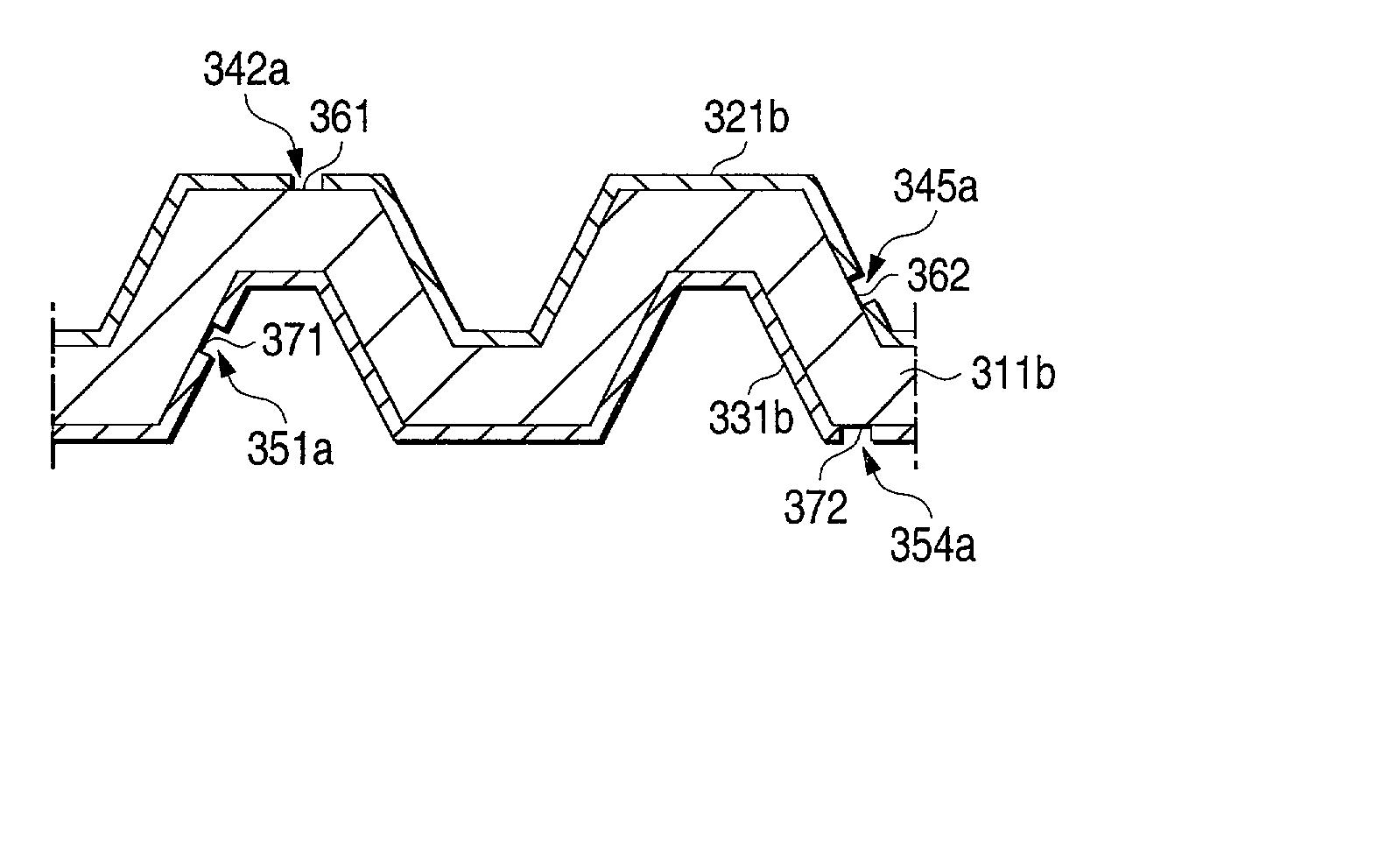
[0136] Inventive samples Nos. 6, 10, 14, 15, 19, and 20 obtained in Examples 1 and 2, which had been produced through cladding and had a noble-metal layer, were shaped by pressing to form grooves having a width of 2 mm and a depth of 1.0 mm with a pitch of 6 mm as shown in FIG. 5. Thus, metallic separators for polymer electrolyte fuel cells (PEFC) were produced which had dimensions of 32.times.32 mm. These metallic separators for polymer electrolyte fuel cells (PEFC) were used as test pieces to conduct a contact electrical resistance test and a corrosion resistance test by the following methods. The results obtained are shown in Table 3.

[0137] (1) Contact Electrical Resistance Test

[0138] A test piece of the metallic separator for polymer electrolyte fuel cells (PEFC), which had dimensions of 32.times.32 mm (effective contact area, 3.20 cm.sup.2), was sandwiched between carbon papers. A current of 100 mA (current density, 31 mA / cm.sup.2) was caused to flow through the sandwich under ...

example 4

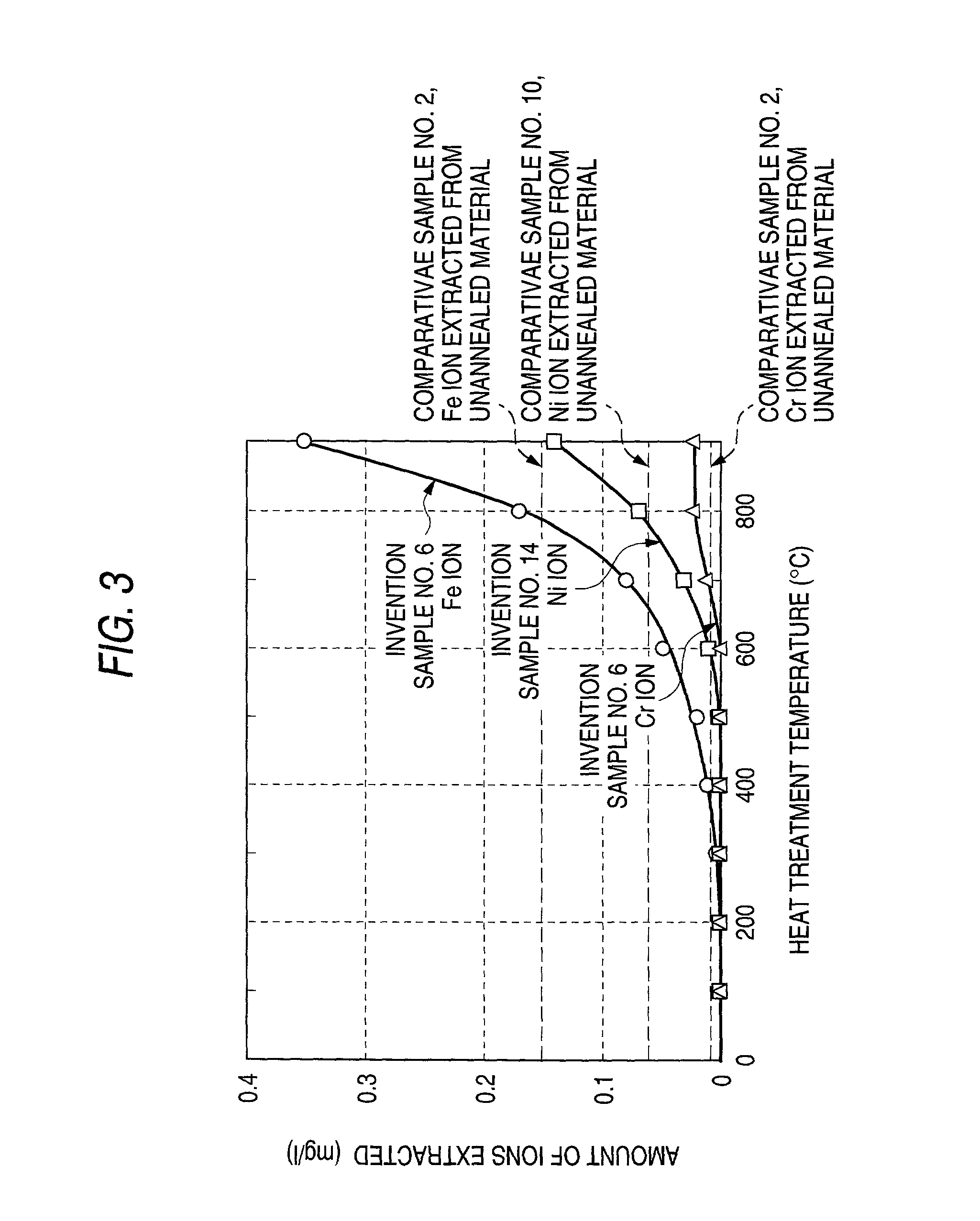
[0141] Inventive sample No. 6 produced in Example 1 and inventive sample No. 14 produced in Example 2 were heated for 15 minutes at each of the heat treatment temperatures shown in Table 4 and then air-cooled to produce samples. Test pieces for a hardness test and corrosion resistance test were cut out of these samples. The metal plates were examined for surface hardness. A corrosion resistance test was conducted by the method used in Example 1. The results obtained are shown in Table 4 and FIG. 3

4 TABLE 4 Inventive sample No. 6 Inventive sample No. 14 Corrosion resistance test Corrosion resistance test Heat treatment Hardness after (ions extracted) Hardness after (ions extracted) temperature heat treatment (mg / L) heat treatment (mg / L) (.degree. C.) (HV) Fe Cr (HV) Ni Cr 25 266 <0.01 <0.01 255 <0.01 <0.01 100 265 <0.01 <0.01 257 <0.01 <0.01 200 267 <0.01 <0.01 255 <0.01 <0.01 300 260 <0.01 <0.01 254 <0.01 <0.01 400 259 0.01 <0.01 246 <0.01 <0.01 500 204 0.02 <0.01 199 0.01 <0.01 600...


PUM

PropertyMeasurementUnit
Fractionaaaaaaaaaa
Fractionaaaaaaaaaa
Thicknessaaaaaaaaaa

Abstract

A highly corrosion-resistant material and a corrosion-resistant member which are improved in corrosion resistance, adhesion, contact electrical resistance, electrical conductivity, airtightness, etc. and are suitable for use as, e.g., a metallic separator for polymer electrolyte fuel cells (PEFC); and a process for producing them. A thin noble-metal layer is formed on the desired part of the surface of a metallic base and then subjected to compression working. The coated base may further be subjected to anticorrosive treatment with a liquid phase containing a peroxide or ozone or with an active gas atmosphere.

Description

[0001] The present invention relates to a corrosion-resistant metallic material or member, a metallic separator for fuel cells which comprises the metallic member, and a process for producing them. More particularly, the invention relates to a highly corrosion-resistant material or member improved in corrosion resistance, adhesion, contact electrical resistance, electrical conductivity, airtightness, etc. and suitable for use as a metallic separator for polymer electrolyte fuel cells (PEFC), and to a process for producing the same.DESCRIPTION OF THE RELATED ART[0002] In applications where corrosion resistance is required, highly corrosion-resistant materials such as, e.g., stainless steel, nickel-based alloys, titanium, and titanium alloys have hitherto been used as they are, or materials obtained by plating steel, stainless steel, or the like with copper, nickel, chromium, or the like have been used. In applications where higher corrosion resistance is required, materials obtained ...

Claims


Application Information

Patent Timeline
IPC IPC(8): B32B15/01H01M8/02
CPCB32B15/018H01M8/0202H01M8/0206H01M8/021H01M8/0228H01M8/0254Y10T428/12896Y10S428/938Y10S428/935Y10S428/925Y10T428/12875Y10T428/12889Y02E60/50Y02P70/50
Inventor KANETA, YASUSHITAKAGI, SHINOBUYOSHIDA, HIROAKISUZUKI, YOSHIHISASHINKAWA, MASAKI
Owner DAIDO STEEL CO LTD
Learn More