
Solid oxide fuel cell stack and method of manufacturing the same

a technology of solid oxide fuel cell and stack, which is applied in the direction of cell components, final product manufacturing, sustainable manufacturing/processing, etc., can solve the problems of series resistance component improvement still remains, form the interconnection itself, and improve the series resistance component. , to achieve the effect of high resistance to high temperature oxidation atmosphere, high temperature reduction atmosphere, and fuel cell stack miniaturization

Inactive Publication Date: 2003-01-16
NISSAN MOTOR CO LTD
View PDF4 Cites 29 Cited by
  • Summary
  • Abstract
  • Description
  • Claims
  • Application Information

AI Technical Summary

Benefits of technology

[0014] To solve these problems, an object of the present invention is to provide a planar fuel cell stack which shows low series resistance, and is small-sized with high reliability.
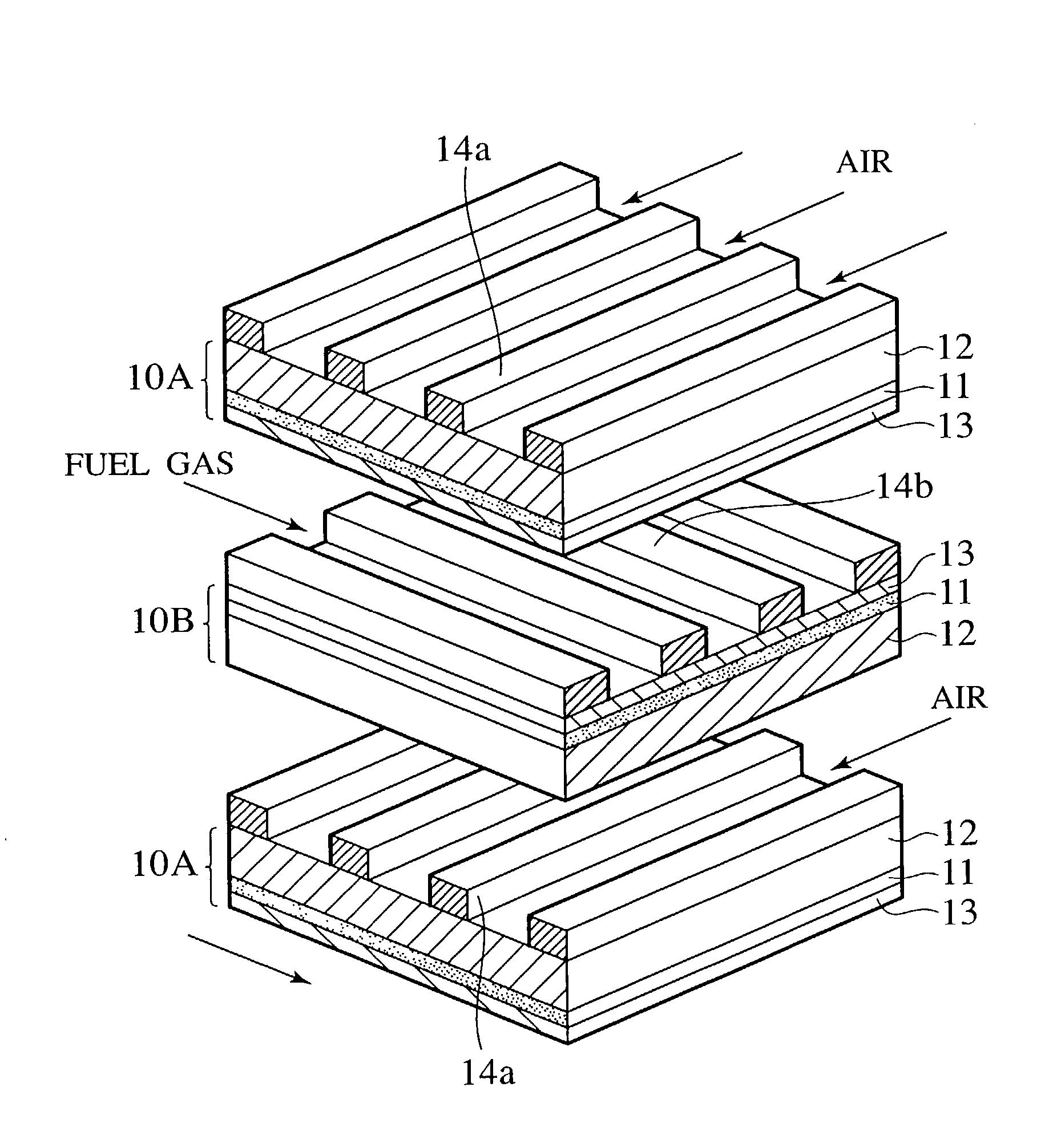
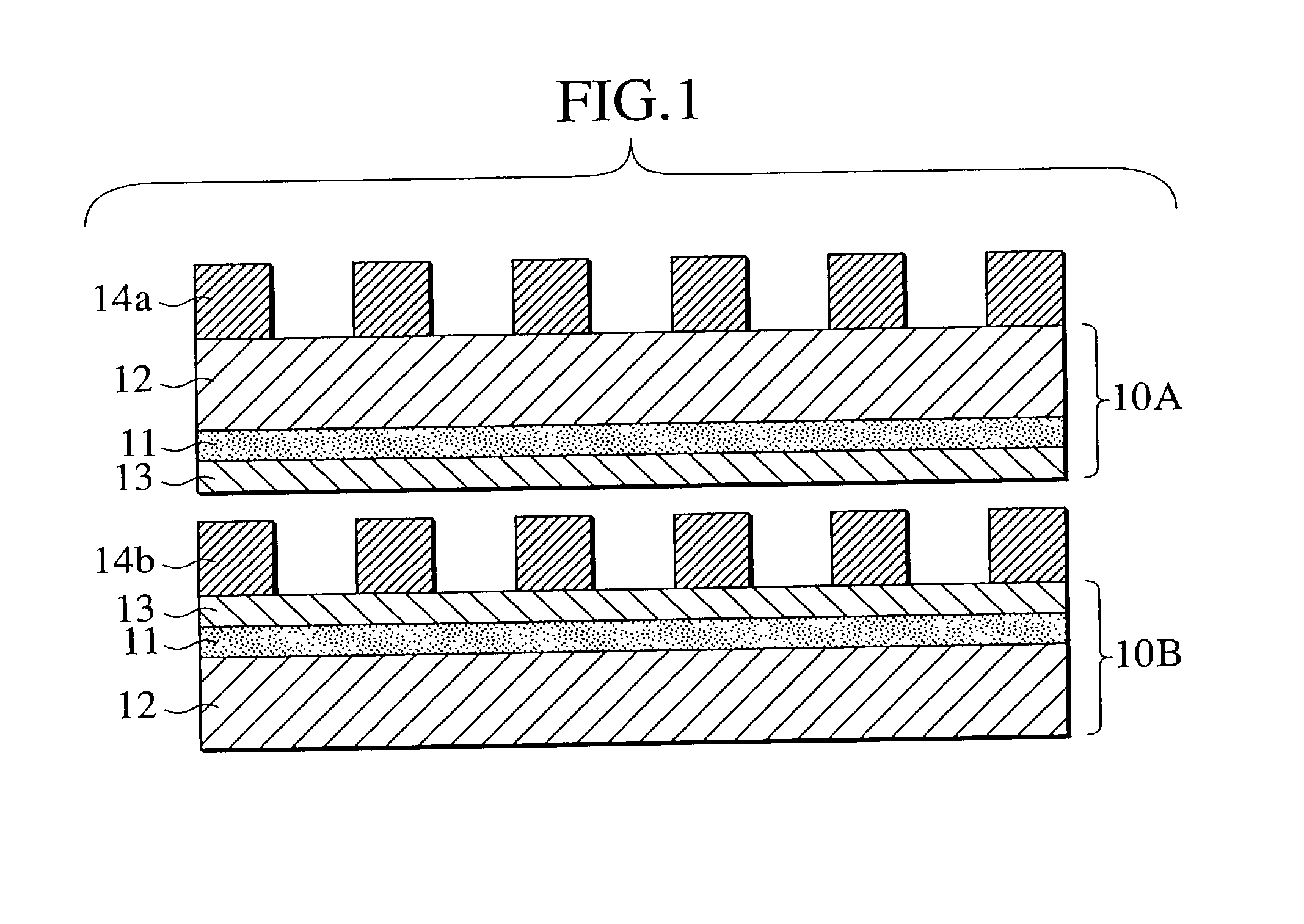
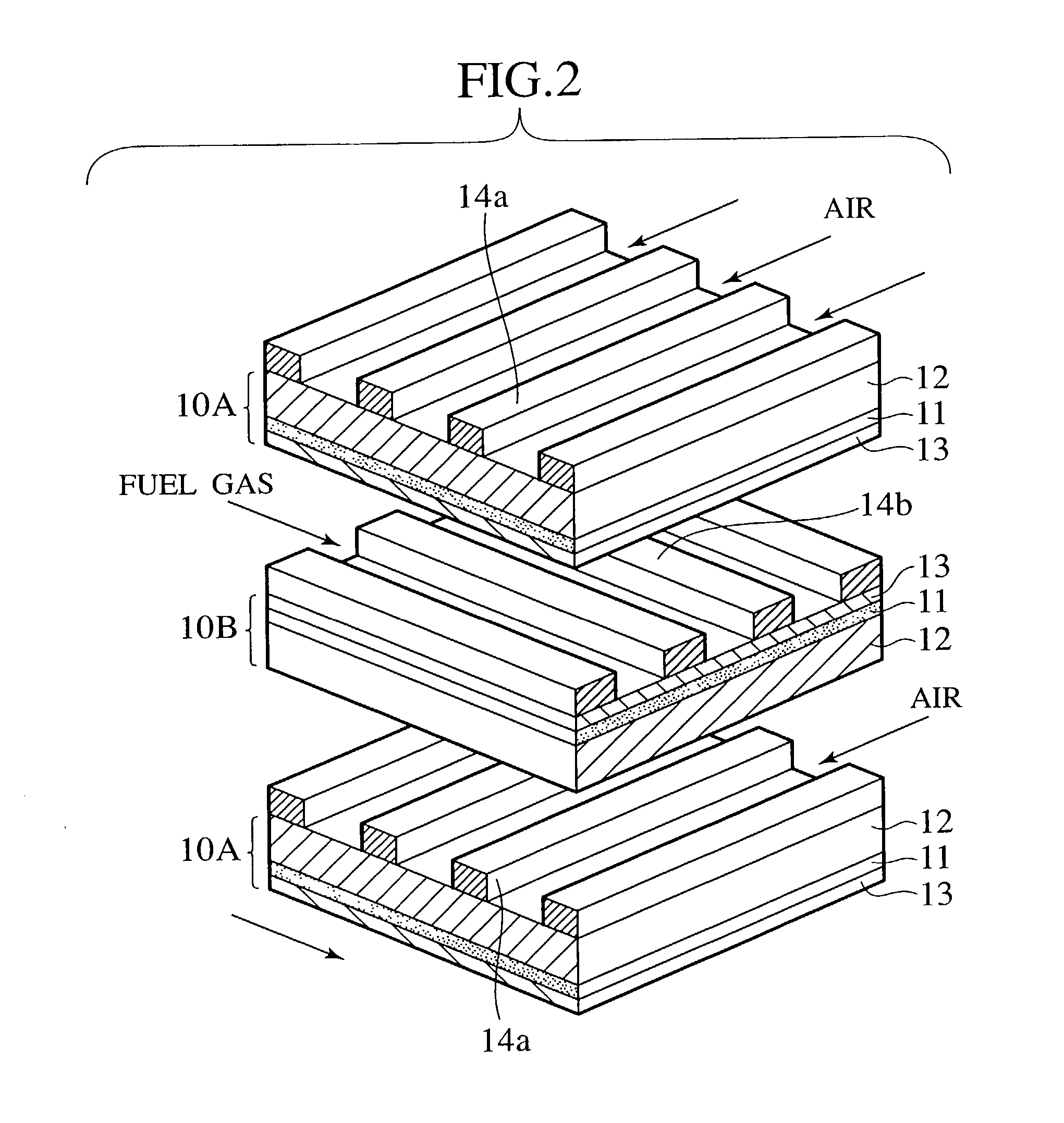
[0020] Accordingly, the gas flow path does not need to be formed by an interconnect and a separator, and the fuel cell stack can be constituted only by the cell plates. Thus, the fuel cell stack can be miniaturized. Moreover, since junction surfaces of the first and second cell plates are formed of the same material and the first and second cell plates are jointed with each other in these junction surfaces, occurrence of cracks in a junction portion of the first and second cell plates owing to a difference of a thermal expansion coefficient between them can be prevented.
[0022] Moreover, the interconnect and the separator are unnecessary, and the fuel cell composed of the thin film solid electrolyte layer, the fuel electrode layer and the air electrode layer can be formed in the opening portion of the substrate in each cell plate. Accordingly, a series resistance of the stack can be reduced.

Problems solved by technology

Therefore, a problem of improvement in a series resistance component within the fuel cell still remains.
Moreover, since the interconnect that is a rectangular body, which serves also as a partition wall of the gas flow path, is located on the electrode, it is impossible to form the interconnect itself in a form of a thin film, and a problem of improvement in a series resistance component still remains, too.
Therefore, it is impossible to increase electromotive force of the fuel cell.
To operate the fuel cell at a high operation temperature causes a problem in costs of materials and reliability on the operation.

Method used


Image

  • Solid oxide fuel cell stack and method of manufacturing the same
  • Solid oxide fuel cell stack and method of manufacturing the same
  • Solid oxide fuel cell stack and method of manufacturing the same

Examples


examples

[0067] An embodiment of the present invention will be described below.

[0068] 1) Treatment of Substrate

[0069] As the substrate, a (100) orientation single-crystal silicon substrate having a diameter of 5 inches and a thickness of 0.65 mm, one surface of which was mirror-polished, was used as the substrate. Antimony was previously doped to this substrate, and its resistively was 10 to 11 .OMEGA.cm. The substrate was cut to a square shape of 5 cm square by a dicing saw so that each side thereof is made to be (110) oriented. The substrate which was processed to a square shape was subjected to a dipping treatment for 10 minutes in a mixed solution of water:hydrogen peroxide:ammonium hydroxide=5:1:0.05, which was kept at 90.degree. C. Thereafter, the substrate was dipped in 5% hydrofluoric acid aqueous solution for one minute and then dipped in pure water for one minute. Then, the substrate was taken out therefrom, followed by drying the substrate by ejecting nitrogen gas thereto. Immedia...


PUM


Abstract

A solid oxide fuel cell stack in which first and second cell plates are alternately stacked. The first cell plates comprises a substrate having a plurality of opening portions, a groove which extends through the plurality of opening portions formed on a lower surface of the substrate, a solid electrolyte layer which covers the opening portion formed on an upper surface of the substrate, a fuel electrode layer which covers the opening portions formed on the solid electrolyte layer, and an air electrode layer formed on the lower surface of the substrate so as to extend along the opening portions and the groove. The second cell plates has a structure in which the air electrode layer is replaced with the fuel electrode layer in the first cell plate. In this fuel cell stack, the air electrode layer of the first cell plate faces the air electrode layer of the second cell plate, and the fuel electrode layer of the first cell plate faces the fuel electrode layer of the second cell plate. A method of manufacturing the solid oxide fuel cell stack comprises preparing the first cell plate, preparing the second cell plate, alternately stacking the first and second cell plates, and collectively sintering the stacked first and second cell plates.

Description

[0001] The present invention relates to a stack used for a solid oxide fuel cell and a method of manufacturing the same, more specifically to a stack for use in a solid oxide fuel cell capable of being made to be small and thin without using a separator or an interconnect with high reliability, a method of manufacturing the same and a solid oxide fuel cell.[0002] A fuel cell is composed of a solid electrolyte showing ion conductivity such as oxygen ion and proton, a porous air electrode (oxidation electrode: cathode) on one side surface of the solid electrolyte and a fuel electrode (reduction electrode: anode) on the other side surface of the solid electrolyte. Oxidation gas containing oxygen gas is supplied to the air electrode, and reduction gas containing hydrogen and hydrocarbon gas is supplied to the fuel electrode. These gases electrochemically react with each other through the solid electrolyte, thus generating electromotive force.[0003] However, the electromotive force obtai...

Claims


Application Information

Patent Timeline
IPC IPC(8): H01M8/02H01M8/12H01M8/24
CPCH01M8/0202H01M8/1206H01M8/1213H01M8/1226H01M8/2425H01M8/2435H01M2300/0074Y02E60/521Y02E60/525H01M8/1231Y02P70/50Y02E60/50H01M8/2404H01M8/2432H01M8/02H01M8/12H01M8/24
Inventor HARA, NAOKIKUSHIBIKI, KEIKOSATO, FUMINORIYAMANAKA, MITSUGUUCHIYAMA, MAKOTOHATANO, MASAHARU
Owner NISSAN MOTOR CO LTD
Learn More