Eureka AIR delivers breakthrough ideas for toughest innovation challenges, trusted by R&D personnel around the world.

Low-pressure chip packaging type junction box and processing method thereof for solar power generation assembly

Active Publication Date: 2022-03-01
JIANGSU TONGLIN ELECTRIC
View PDF9 Cites 0 Cited by
  • Summary
  • Abstract
  • Description
  • Claims
  • Application Information

AI Technical Summary

Benefits of technology

[0015]An aspect relates to a low-pressure chip packaging type junction box for a solar power generation assembly and a processing method thereof, which can solve problems of large stress, high local temperature and uneven heat dissipation of the photovoltaic module, a low utilization rate of the internal heat dissipation space of the junction box and large investment in product development, integrate techniques relating to development and manufacturing of junction boxes with semiconductor packaging techniques to effectively enhance product performance and meanwhile reduce product cost and development cost and increase a degree of product automation.
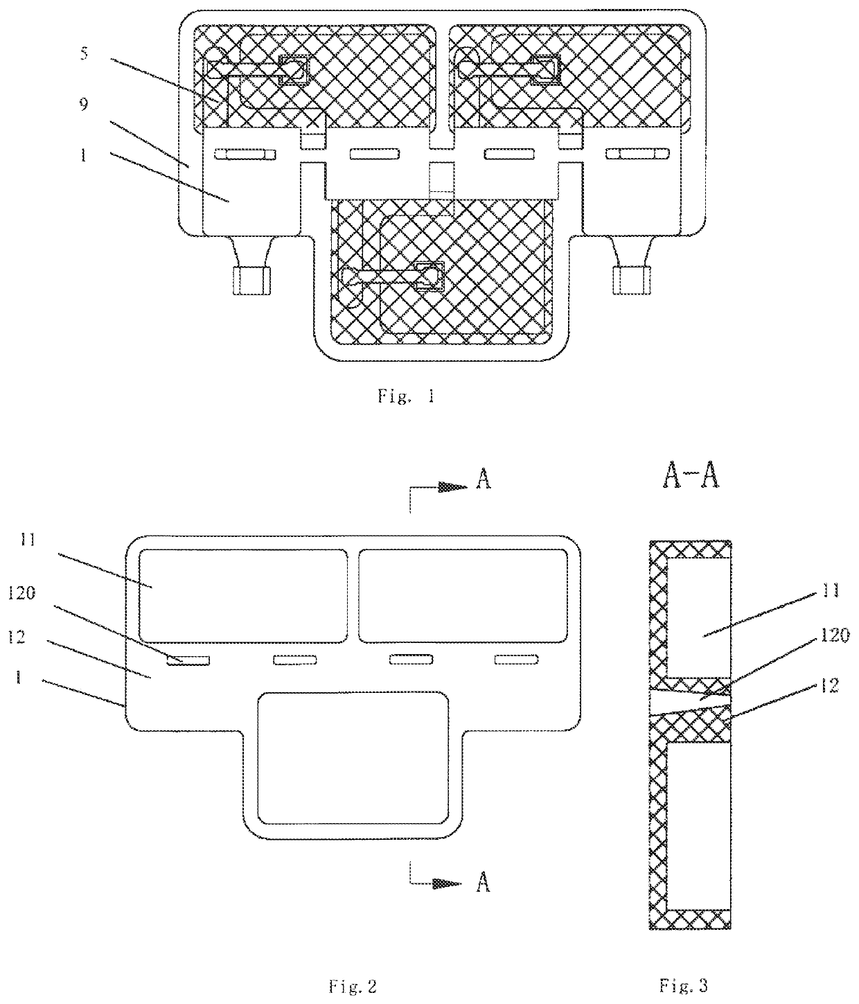
[0036]The embodiments design the box body of the junction box into a plastic body having one or more adhesive storage slot with an opening top (i.e., accommodation recess); and determines the number of accommodation recesses according to the requirements of the junction box model and the requirements of heat dissipation distribution. For a box body having two or more accommodation recesses, the accommodation recesses are arranged in two lines, a transverse bar is arranged between two lines of accommodation recesses, busbar guide holes are arranged on the transverse bar, and threading holes are arranged on lead-out positions of copper conductors so as to place a busbar according to user's application. This distribution mode enables dispersion of heat sources during work of diodes, makes full use of the limited heat dissipation space in the junction box and reduces mutual impact.
[0038]The embodiments use an epoxy resin adhesive with high thermal conductivity and high mechanical strength. Through potting at a low pressure and static curing, the diode chips are packaged for protection and the copper conductors and the box body are fixed in high strength. The production process avoids mechanical impact of jet flow of a high-pressure injection molding material on chips, and pull of the chips resulting from deformation of copper conductors caused by the jet flow of a high-pressure injection molding material;
[0040]Meanwhile, after epoxy resin filled with alumina powder, silica powder or other thermally conductive media in accommodation recesses is cured, the epoxy resin fully contacts the copper conductors in a horizontal direction and a vertical direction to quickly lower working temperature of the chips, improve current passing capacity by 30% and more efficiently raise product performance of the junction box.
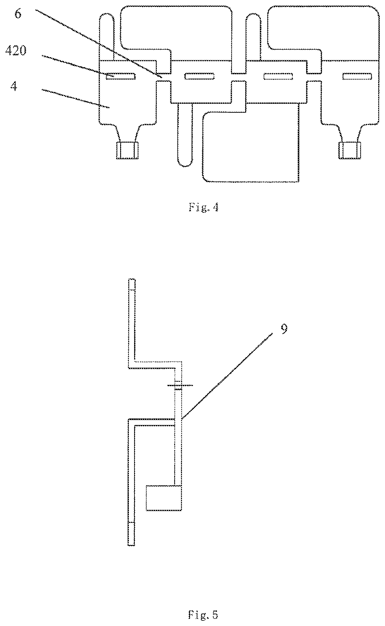
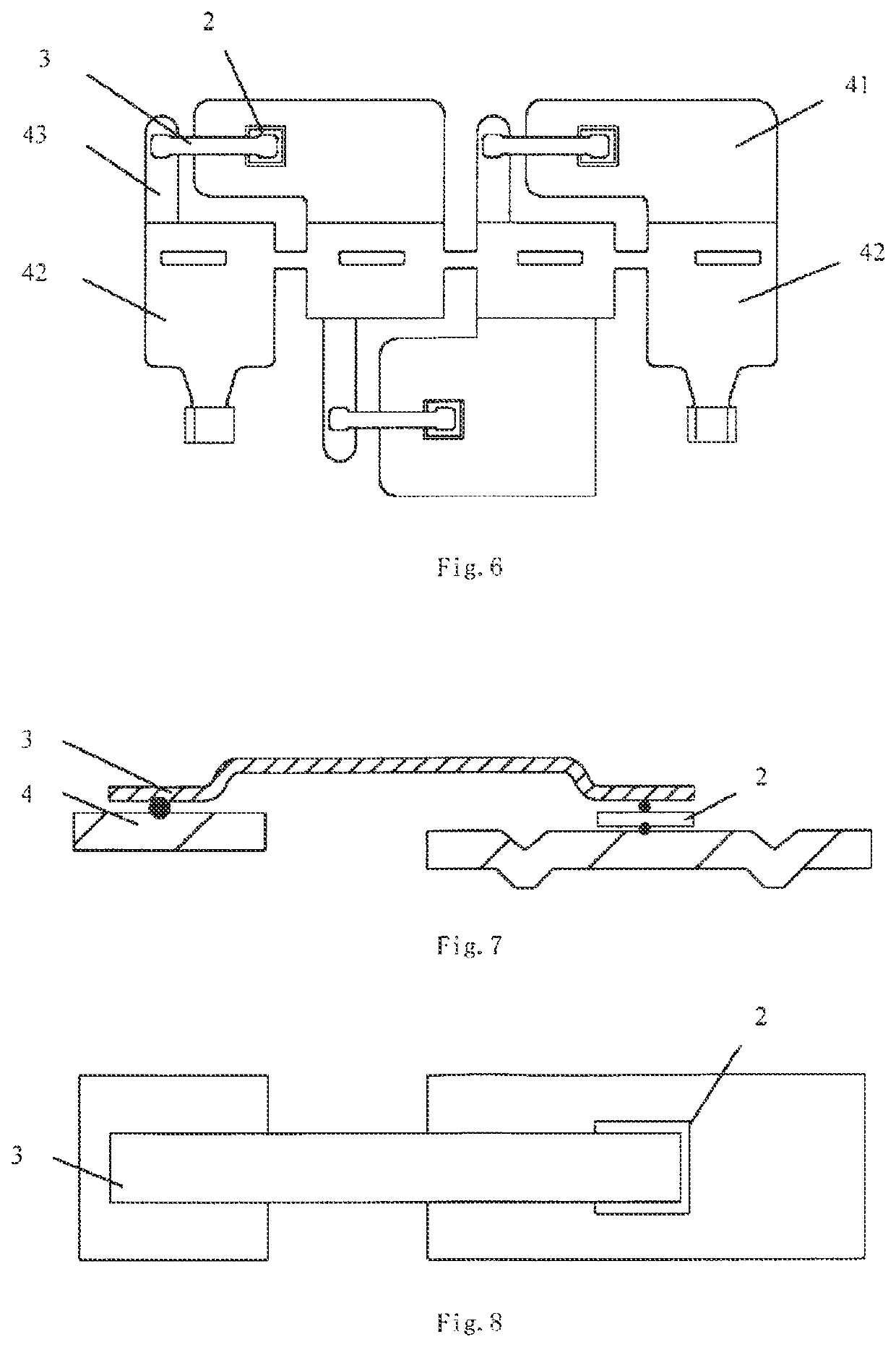
[0041]N+1 copper conductors are connected in series by means of the chips and the connection members. In order to eliminate a pull stress on the chips resulting from relative movement of the copper conductors in the manufacturing process, embodiments of the present invention designs process connection rings or process connecting strips among copper conductors during punching of the copper conductors so that a plurality of copper conductors temporarily forms an integral body. After chip soldering, potting and curing, the process connection rings or process connecting strips are removed by means of drilling or punching.
[0042]The embodiments step over a packaging and manufacturing process of individually packaged diode junction boxes and photovoltaic module junction boxes, and skips work content such as secondary soldering and secondary assembly. The embodiments integrate design and manufacturing of junction boxes with semiconductor diode packaging techniques and avoids potential quality hazard of junction box products arising from secondary soldering and installation; greatly raises development speed of junction boxes; saves the processes of mutual running-in and adjustment of the junction box manufacturer and the semiconductor diode packaging manufacturing; and facilitates a more compact structure of the junction box products, more reasonable use of materials, faster development of products, easier realization of automated production, lower product manufacturing cost and stronger market competitiveness.

Problems solved by technology

Other power generation assemblies connected to the silicon cell in series generate power normally under irradiation of sunlight and current passing the cell in a resistance state will generate large heat, burning down the cell and backing sheet of the assembly.
Therefore, the manufacturing and installation processes of the junction box have many steps and are labor consuming.
Junction boxes produced in the known art meet with difficulty in solving problems about sealing performance, temperature rise and internal gas expansion.
However, in terms of structure and application requirements, the module is fixed inside a junction box still by mounting method, sealant still needs to be filled in the inner chamber of the box body after the solar power assembly manufacturer installs the junction box into a power generation assembly, and the product does not have obvious advantages in production and application.
As a result, the limited heat dissipation space inside the junction box cannot be effectively utilized, thus limiting the passing capacity of working current.
Complex production equipment is required in the production and application of junction boxes to achieve automatic assembly.
1. Most photovoltaic module products adopt an ultrasonic aluminum wire wedge bonding process as shown in FIG. 35. An ultrasonic bonding tool 10 is used to connect aluminum wires to diode chips and photovoltaic modules. This method has two problems. The first, all photovoltaic diodes adopt Schottky process chips. PN junction of a diode in this process is located under a surface aluminum metal layer of the chip. The ultrasonic bonding stress will act on the diode chip. If the pressure and amplitude are large, it is prone to damaging the PN junction and affecting the service life of the product, while if they are small, it is prone to false connection. Therefore, very expensive process equipment needs to be used to meet process requirements and realize stability; the second, as aluminum wires are used as a welding material and inferior to copper and silver in terms of electric conductivity and thermal conductivity, the voltage drop of the photovoltaic module product is high and during work, the photovoltaic module product shows high heat generation, large power consumption and poor heat dissipation.
2. A process of high pressure injection is adopted, as shown in FIG. 36, to wrap a thermosetting resin material around a soldered chip. In this injection process, plastics driven by injection head is sprayed at an extremely high jet speed and pressure into the mold cavity, and directly acts upon the diode chip and the connecting aluminum strip, resulting in a compressive stress of the chip and a pull stress of the aluminum strip from the resin material. The stress concentration in the injection molding process causes deformation of the internal structure of the module, impairing the reliability of the module.
3. As a common practice among existing photovoltaic module products, three diode chips are distributed on one side of a copper conductor and this side is sealed with a thermosetting resin material. When a hot spot effect is locally generated in a photovoltaic assembly, one or two of the chips will start working to generate heat. Owing to the thermal conductivity of the external packaging material and the copper conductor, temperature of heated chips will be quickly transferred to adjacent chips to raise temperature of the adjacent chips. On the moment, the local area of the photovoltaic assembly without a hot spot effect still generates power normally and its power generation voltage reversely acts on the corresponding diode chips. Based on the high temperature characteristics of the Schottky diode chips, the reverse leak current will increase. As the leak current will not be saturated, temperature of the PN junction of the chips will rise further. Hence the reverse leak current increases again, forming a vicious cycle of heat generation of the diode chips. In a serious case, the balance point is exceeded, the diode chips are broken down, and the photovoltaic module product loses effect.
4. In an existing photovoltaic module product, diode chips are put together and wrapped with thermosetting resin. In a working state, heat generated by the diode chips cannot be dissipated fast, restricting the working current of the junction box.
5. Junction boxes produced in the known art all have a process of secondary machining of semiconductors: an individually packaged diode needs to be connected to a copper conductor by means of crimping or reflow soldering; a photovoltaic module needs to be fixed and connected to a plastic tray inside a junction box body by means of push mounting; high temperature of reflow soldering causes various expansions of different materials, which will affect internal stress and compactness of devices; crimpling will make the devices be affected by external pressure, causing plastic burst and cracking of the photovoltaic module and potential quality hazard from pressure;
6. Photovoltaic modules need high development cost and the corresponding relations with junction boxes are singular, unable to adapt to the development of j unction boxes. The requirements for installation match between the two are high, adding difficulty of development match between them.

Method used


Image

  • Low-pressure chip packaging type junction box and processing method thereof for solar power generation assembly
  • Low-pressure chip packaging type junction box and processing method thereof for solar power generation assembly
  • Low-pressure chip packaging type junction box and processing method thereof for solar power generation assembly

Examples


Embodiment Construction

[0081]The embodiments, as shown in FIGS. 1-34, comprise a box body 1, N chips 2, N connection members 3 and N+1 copper conductors 4, with N≥1. At least one accommodation recess 11 is arranged at the box body, and a transverse bar 12 with a top surface higher than a bottom of the accommodation recess is arranged on the box body;

[0082]The shape of the accommodation recess can be designed to be square, oval or polygonal depending on product requirements;

[0083]Distribution of the accommodation recesses in a junction box: When the junction box has one accommodation recess, the accommodation recess is distributed on one side of the junction box; when the junction box has two or more accommodation recesses, the accommodation recesses are distributed on two sides or periphery of the junction box; the purpose is to maximally disperse heat sources and make use of limited heat dissipation space of the junction box;

[0084]N of the N+1 copper conductors 4 correspond to the N chips one to one. Chi...


PUM

PropertyMeasurementUnit
pressureaaaaaaaaaa
resistanceaaaaaaaaaa
poweraaaaaaaaaa

Abstract

Provided is a low-pressure chip packaging type junction box for a solar power generation assembly and a processing method thereof, and more particularly, relates to a low-pressure chip packaging type junction box for a solar power generation assembly integrating techniques relating to development and manufacturing of junction boxes with semiconductor packaging techniques to increase a degree of product automation and a processing method thereof. The low-pressure chip packaging type junction box for a solar power generation assembly comprises a box body, N chips, N connection members, and N+1 copper conductors, where N≥1. At least one accommodation recess is arranged at the box body. The box body is provided with a transverse bar. Chip installation positions are arranged at N copper conductors. The N+1 copper conductors are provided with lead-out positions positioned at a top surface of the transverse bar. The chip is welded and fixed to the installation position at the copper conductor.

Description

CROSS-REFERENCE TO RELATED APPLICATIONS[0001]This application claims priority to PCT Application No. PCT / CN2017 / 114777, having a filing date of Dec. 6, 2017, which is based on CN Application No. 201710142905.6, having a filing date of Mar. 10, 2017, the entire contents both of which are hereby incorporated by reference.FIELD OF TECHNOLOGY[0002]The following relates to a junction box for a solar power generation assembly, particularly to a low-pressure chip packaging type junction box for a solar power generation assembly and a processing method thereof.BACKGROUND[0003]A junction box for a solar power generation assembly is an important component installed in a solar power generation assembly. It plays a role in providing bypass protection for cells in the assembly and transmitting out power generated by the assembly. A solar power system connects a number of power generation assemblies in series and / or parallel via output cables in the junction boxes of the assemblies as well as con...

Claims


Application Information

Patent Timeline
Patent Type & Authority Patents(United States)
IPC IPC(8): H02S40/34H01L31/02H01L31/052H01L31/18
CPCH02S40/34H01L31/0201H01L31/052H01L31/18Y02E10/50
Inventor LI, QIANJINZHU, DIBAOZHANG, DAOYUANJIANG, LIWANG
Owner JIANGSU TONGLIN ELECTRIC
Why Eureka
Eureka Blog
Learn More