
Method for manufacturing bone implants and bone implant

a bone implant and bone implant technology, applied in the field of bone implants and bone implants, can solve the problems of large tissue loss (so-called critical loss), complex multi-stage manufacturing process, and large thickness of layers obtained, and achieves the effects of facilitating the adjustment of the implant shape, good quality, and effective stimulation of cell proliferation and bone tissue growth

Active Publication Date: 2022-03-01
INST WYSOKICH CISNIEN POLSKIEJ AKADI NAUK
View PDF6 Cites 0 Cited by
  • Summary
  • Abstract
  • Description
  • Claims
  • Application Information

AI Technical Summary

Benefits of technology

The invention is a method to make bone implants that can stimulate bone growth. The implant is coated with a material called hydroxyapatite which is effective in promoting bone growth. The results from in vivo testing with rabbits show that the implant is well-received by the body, with new bone tissue growing within three months. The coated implant is durable and can be adjusted in shape without losing its beneficial properties. The manufacturing process is short and requires low temperatures, which allows for the use of a wider range of materials for the supporting structure of the implant. This method also results in significant cost savings due to the low process temperature.

Problems solved by technology

Presently, there are many treatment methods for small defects in bones, but still no solution for large tissue loss (so-called critical loss) is known.
The disadvantages of the method for covering implants disclosed there are complex multi-stage manufacturing process and a considerable thickness of the layers obtained.
The disadvantage of the described method is the need for forming pores in the layer.
However, the actual effectiveness of such layers has not been specified.
A lot of these methods can only be used to produce layers on materials resistant to temperatures above 200° C., thus precluding the use of this methods for most plastics.
The advantage of this method is the good adhesion of the layers to the substructure, but its disadvantage is the need for the transition metal layer and the process temperature greater than 200° C. No information on the structure and thickness of this layer has been specified.
This extends the duration of the process and increases the possibility of introducing contamination.
3174-3183] S. Goodman and Z. Yao reveal the problem of insufficient mechanic resistance of such a layer in terms of its adhesion to the substructure.
The disadvantage of this method is a length of the process, as well as weak binding between the polymer and the ceramics.
The drawback of this technology is the necessity of immersing the coated material in a number of different solutions and a long time needed for layer preparation.
The disadvantage of this solution is the long time needed for preparing the coating, at least 12 hours of soaking in a solution of calcium and phosphate ions, two hours of freezing and lyophilisation step taking several hours.
The advantage of this method is a short duration of the process, however a relatively high process temperature of this method makes it unsuitable for polymer substructures, particularly those with low softening temperature and poor chemical resistance.
There is, however, no possibility of a uniform coating of porous substructures, and possibility of coating with nano-particles of hydroxy-apatite has not been even suggested.
However, this methods is limited only to coating conductive materials or materials covered with pre-added conductive layer.
In addition, it is difficult or impossible to cover the whole volume of the material with a small size of the pores and a complicated geometry.
Also in this solution, there are no guidelines as to the use of ultrasound for obtaining hydroxyapatite layers.
Disclosed nano-powder is intended for filling undesirable cavities in bone tissue, but in the said application there are no guidelines as to the application of such a nano-powder in the production of implants and implant layers.
This report does not contain any guidance on durable coating with the powder of spatially complex bone implants, especially ones with high flexibility.
However, this publication does not disclose any details of the coating and the obtained coating properties, while it is well known that in nanotechnology the properties of the nano-particles strongly depend on their size, shape, chemical composition of molecules attached to their surfaces and their inner structure.

Method used


Image

  • Method for manufacturing bone implants and bone implant
  • Method for manufacturing bone implants and bone implant
  • Method for manufacturing bone implants and bone implant

Examples


example 1

Porous Polymer Implant

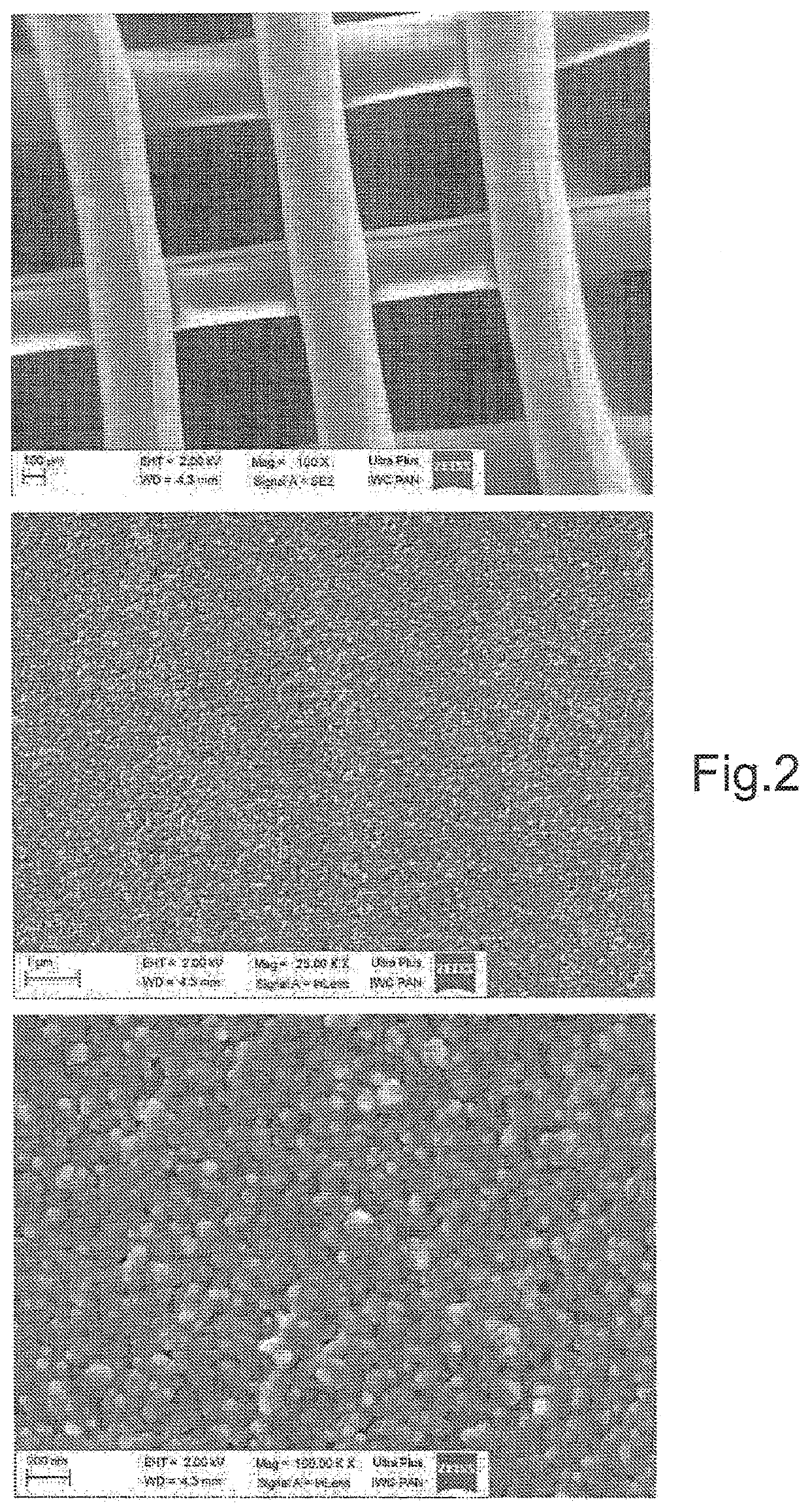
[0053]Supporting structure 1 of the implant was made of biodegradable polymer-poly-caprolactone (PCL). It has a form of 3-dimensional scaffold, measuring 4×6 mm, made from polymer fibers by printing technology of the spatial “rapid prototyping” which is described in W. Święszkowski et al., “Repair and regeneration of ostechondral defects in the articular joints” [Biomolecular Engineering, 2007 24 (5): pp. 489-95] The supporting structure 1 is characterized by the porosity of approx. 41%. As the coating material of the supporting structure a nano-powder of hydroxyapatite GoHAP was used, with a molar ratio (Ca / P) of 1.65, containing 5% by weight of structural water. This powder (in amount of 0.1% by weight) was mixed in 50 ml vessel 2 with deionized water to form a homogeneous suspension 3, wherein the external phase is water and the internal phase is hydroxyapatite. The supporting structure 1 was rinsed with distilled water, and then fitted to the stand 4 for im...

example 2

Porous Ceramic Implant

[0056]In order to produce a ceramic implant coated with a layer of nano-particles of hydroxyapatite a supporting structure in a form of porous ceramic pellets was used. For the production of pellets a method of uniaxial pressing of the β-TCP powder was used with a pressure force of 15 kN. For the production of one sample 3.06 g of powder was taken. In order to achieve structural microporosity a heat treatment method was used in which said pallet was subjected to 1200° C. for a period of two hours. The pellets were then examined for signs of porosity using methods of computer microtomography and Archimedes method. According to the μ-CT calculations a porosity of 49% was reached, while the result of the analysis by the Archimedes method was 52% (+ / −2.6%). The coating processes with GoHAP of the prepared ceramic implant supporting structure was carried out in a manner analogous to the first example, wherein a nano-powder with a water content of 5% by weight was us...

example 3

Monolithic Metallic Implant

[0058]In order to produce a monolithic metal implant a supporting structure was used in a form of a titanium screw having a diameter of 5 mm and a length of 150 mm, dedicated to arthroscopy. The screw was coated with a layer of GoHAP nano-particles by ultrasonic effect on the aqueous suspensions described in detail in the first embodiment, wherein a powder has a diameter of not more than 6 nm, a structural water content of 3% by weight, molar ratio of calcium to phosphorus (Ca / P) of 1.60. Based on the SEM image analysis it was found that the resulting coating has morphological properties characteristic for the initial GoHAP powder. The titanium screw was coated with a uniform layer of hydroxyapatite having a thickness of 200 nm, covering 85% of its surface (FIG. 8).


PUM

PropertyMeasurementUnit
particle sizeaaaaaaaaaa
molar ratioaaaaaaaaaa

Abstract

The method of making an implant consists on coating of a supporting structure (1) with synthetic hydroxyapatite by immersing the supporting structure (1) in a suspension (3) and triggering of a cavitation in a portion of the suspension (3) being in contact with the supporting structure (1). The suspension (3) is formed by a liquid external phase, advantageously water, and internal phase, i.e. particles of synthetic hydroxyapatite having an average particle size not exceeding 100 nm and containing structural water in an amount from 2 to 6% by weight. The implant is coated with the above described hydroxyapatite subjected to cavitation and a thickness of 50 nm to 1000 nm, advantageously 50 nm to 300 nm.

Description

TECHNICAL FIELD[0001]The invention regards a method of producing bone implants having a character of supporting structure at least partially coated with a synthetic hydroxyapatite and bone implants for use in orthopaedic surgery, trauma surgery (traumatology), regenerative implantology, which facilitate or accelerate the regeneration of bone tissue.BACKGROUND ART[0002]In medicine, particularly in orthopaedics, dentistry and traumatology, and in the treatment of bone defects caused by the removal of the tumour, implants, also known as scaffolds for bone tissue regeneration, are used in order to induce or accelerate regeneration of the bone tissues by the organism; tissue that was lost as a result of trauma, surgery of cancer removal, orthopaedic surgery, dental surgery, tooth extraction, other causes or improvement of aesthetics. For the production of such implants various kinds of synthetic biomaterials (metals, ceramics, synthetics—polymers, composites) as well as natural materials...

Claims


Application Information

Patent Timeline
Patent Type & Authority Patents(United States)
IPC IPC(8): A61L27/32A61L27/56A61L31/08A61L27/10A61L27/12A61L27/14
CPCA61L27/32A61L27/10A61L27/12A61L27/14A61L27/56A61L31/086A61L2400/12A61L2420/02A61L2430/02
Inventor SWIĘSZKOWSKI, WOJCIECHCHUDOBA, TADEUSZKUŚNIERUK, SYLWIAKĘDZIERSKA, ALEKSANDRAWOŹNIAK, BARTOSZROGOWSKA-TYLMAN, JULIASMOLEŃ, DARIUSZPIETRZYKOWSKA, ELZBIETALOJKOWSKI, WITOLDWOJNAROWICZ, JACEKGEDANKEN, AHARONLOCS, JANISZALITE, VITAPILMANE, MARASALMA, ILZE
Owner INST WYSOKICH CISNIEN POLSKIEJ AKADI NAUK
Learn More