
METHOD AND SYSTEM FOR SETTING TIMING OF PHASE MODULATION OF xPSK TRANSMITTER

a technology of phase modulation and xpsk transmitter, which is applied in the field of optical transmitters, can solve the problems of difficult manufacturing, no way to optimize timing, and no way to guarantee the match within a symbol period for high symbol rate, and achieves the effect of compact and less expensive, simple and quick method

Active Publication Date: 2011-04-21
NEC CORP
View PDF5 Cites 26 Cited by
  • Summary
  • Abstract
  • Description
  • Claims
  • Application Information

AI Technical Summary

Benefits of technology

[0019]An object of the present invention is to provide a simple and quick method of and a compact and less expensive system for setting and optimizing the timing of the phase modulation performed with a tuning range wider than one symbol period and valid for both serial and parallel high order xPSK transmitters.
[0020]In an aspect of the present invention, a method is provided with: setting a timing of phase modulation by a target phase modulator within an optical transmitter which performs phase shift keying of an order equal to or higher than four. The setting step includes: feeding a specific pattern to the optical transmitter to allow the xPSK transmitter to emit an optical carrier in accordance with the specific pattern; receiving the optical carrier by a delay interferometer; converting a light signal emitted from the delay interferometer into an electrical signal; detecting a peak to peak value of the electrical signal. The timing of the phase modulation by the target phase modulator is set so as to minimize the peak to peak value of the electrical signal.

Problems solved by technology

This scheme has the advantage of integration but these devices are difficult to manufacture and voltage driving is not trivial because higher amplitudes are required.
Precise designing and manufacturing of the serial high order transmitter may provide a fair match for the timing; however, it offers no way to guarantee the match within a symbol period for high symbol rates.
Moreover, there is no way to optimize the timing.
However, this method cannot be used to set the timing of modulation for a serial transmitter.
Moreover, this method has a narrow tuning range limited to one symbol on the timing.
However, this method has a narrow tuning range limited to one symbol on the timing and requires an optical spectrum analyzer, which is bulky and expensive measurement equipment.

Method used


Image

  • METHOD AND SYSTEM FOR SETTING TIMING OF PHASE MODULATION OF xPSK TRANSMITTER
  • METHOD AND SYSTEM FOR SETTING TIMING OF PHASE MODULATION OF xPSK TRANSMITTER
  • METHOD AND SYSTEM FOR SETTING TIMING OF PHASE MODULATION OF xPSK TRANSMITTER

Examples


Embodiment Construction

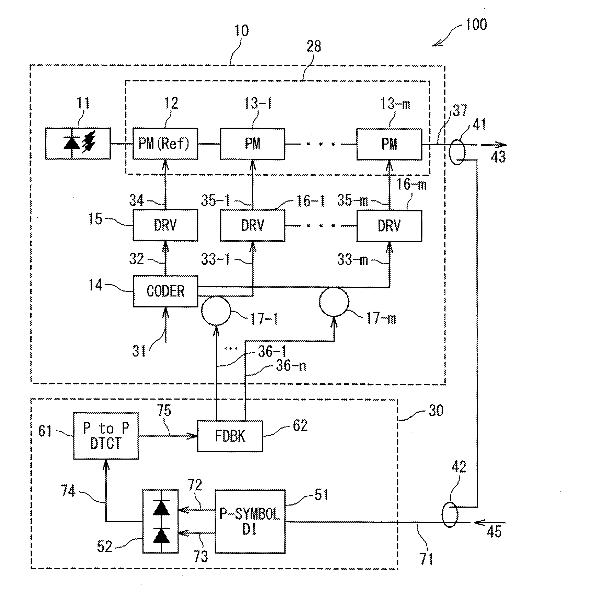
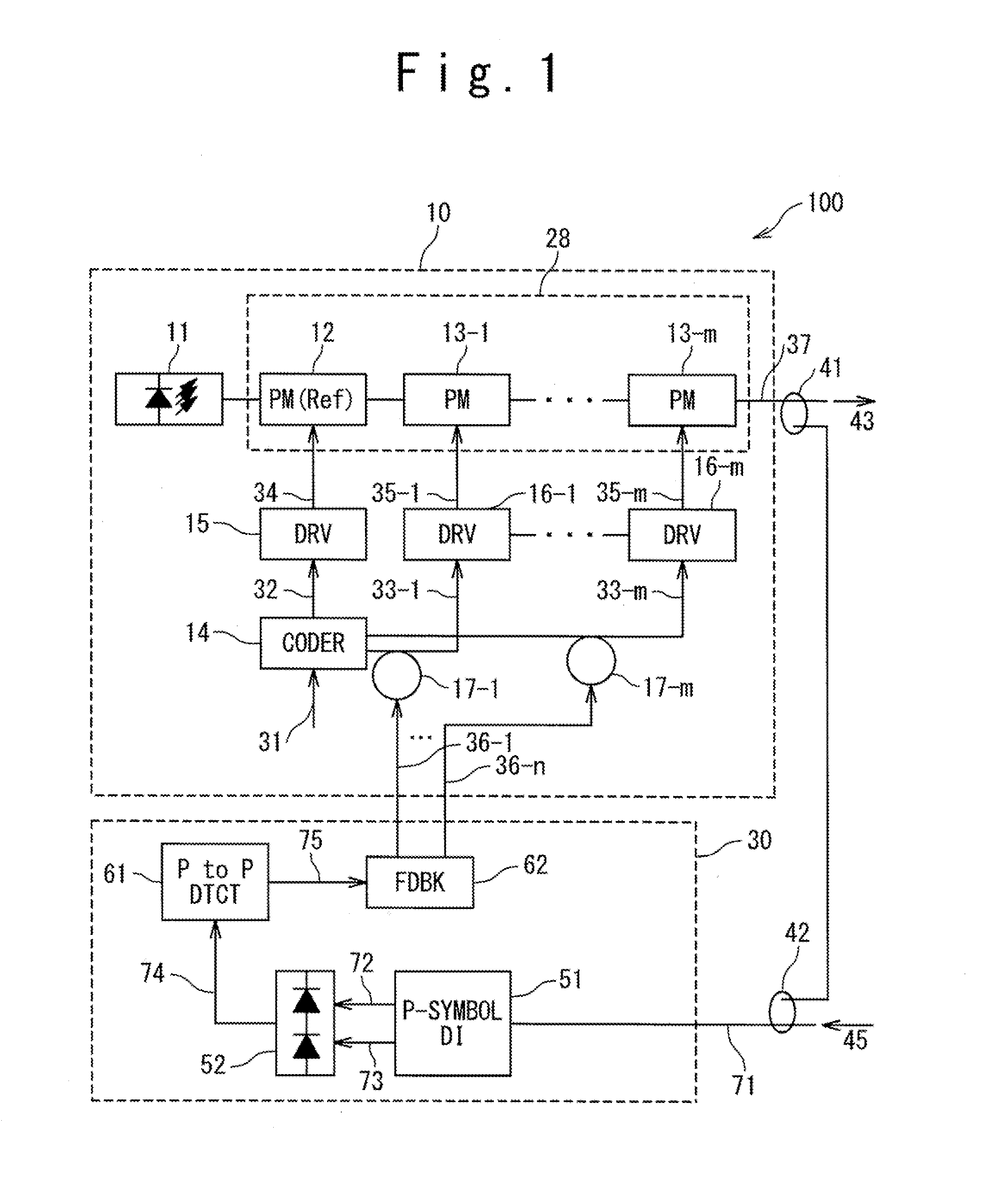
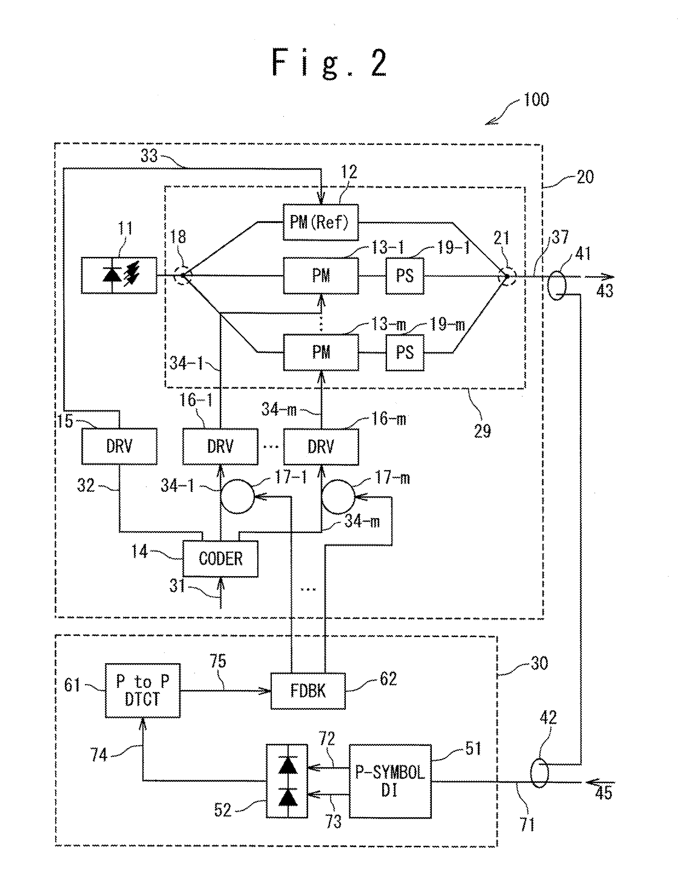
[0039]FIG. 1 is a schematic representation of an exemplary xPSK transmitter 100 which order is four or higher than four, in one exemplary embodiment of the present invention. The system 10 is an optical sub-module, the system 30 is a control system 30, components 41 and 42 are respectively a divider and a coupler. The sub-module, the system 30 as well as the components 41 and 42 may be integrated on the serial xPSK transmitter 100.

[0040]Alternatively, the sub-module may be considered as an independent serial xPSK transmitter and the system 30 as well as components 41 and 42 as external means to set the timing of modulation of the sub-module 10.

[0041]The sub-module 10 emits a light signal 37 modulated with high order Phase Shift Keying (xPSK) which order x of modulation is 2n, where n is strictly higher than 2. The control system 30 is adapted to monitor the light signal 37 and to provide setting of the timing of the phase modulation in the sub-module 10 in response to the light sign...


PUM


Abstract

A method is provided for setting a timing of phase modulation by a target phase modulator within an optical transmitter which performs 2n order phase shift keying, n being a natural number equal to or more than two. The method is provided with: feeding a specific pattern to the optical transmitter to allow the xPSK transmitter to emit an optical carrier in accordance with the specific pattern; receiving the optical carrier by a delay interferometer; converting a pair of light signals emitted from constructive and destructive outputs of the delay interferometer into an electrical signal; detecting a peak to peak value of the electrical signal; and setting the timing of the phase modulation by the target phase modulator so as to minimize the peak to peak value of the electrical signal.

Description

TECHNICAL FIELD[0001]The present invention relates generally to an optical transmitter emitting a light signal modulated with high order Phase Shift Keying (xPSK), more particularly, to timing control of phase modulation within an xPSK optical transmitter of the order x, where x is equal to or higher than four.BACKGROUND ART[0002]An optical sub-module is provided within an optical communication system and used to emit light signals into a transmission medium. An optical sub-module, which emits light signals withholding the information of an electrical data pattern applied at the input interface of the sub-module, may be referred as a transmitter. An optical sub-module, which has a part receiving light signal and converting its information into an electrical signal can be referred as a receiver. An optical sub-module, which has a part being referred as a transmitter and another part being referred as a receiver, may be referred as a transponder.[0003]Transmitters can use several opti...

Claims


Application Information

Patent Timeline
Patent Type & Authority Applications(United States)
IPC IPC(8): H04B10/04H04B10/43
CPCH04B10/5561H04B10/505
Inventor DE GABORY, EMMANUEL LE TAILLANDIERSHIOIRI, SATOMI
Owner NEC CORP
Learn More