
Controlled thermal coefficient product system and method

a technology of thermal coefficient and product system, applied in the maintenance of heating chambers, metal-working equipment, lighting and heating equipment, etc., can solve the problems of low thermal conductivity and fracture toughness of nte, limited behavior, and only linear nte respons

Active Publication Date: 2020-11-03
TEXAS A&M UNIVERSITY
View PDF6 Cites 2 Cited by
  • Summary
  • Abstract
  • Description
  • Claims
  • Application Information

AI Technical Summary

Benefits of technology

This approach enables the production of materials with precisely controlled thermal expansion properties, addressing the limitations of prior art by allowing for tailored thermal expansion coefficients within a predetermined range, enhancing their suitability for diverse applications.

Problems solved by technology

Unfortunately, most materials exhibiting NTE have low thermal conductivity and fracture toughness (e.g., ceramics), or the NTE response is only linear over a very small temperature range (e.g., Invar alloys).
However, this behavior is usually limited to a certain temperature range or to materials that may not be suitable for a wide range of applications.
However, this negative thermal expansion only occurs over a relatively small temperature range, and further, Invar may have a propensity to creep.
However, these materials typically cannot be used in applications with tension and compression stresses comparable to what a metallic material can withstand, nor in the same extreme conditions as a metallic material.
This mechanism used for tailoring thermal expansion may be explained in a variety of ways as discussed below, including that the martensitic transformation may have previously been difficult to achieve because that mechanism was in competition with dislocation plasticity in the first phase.
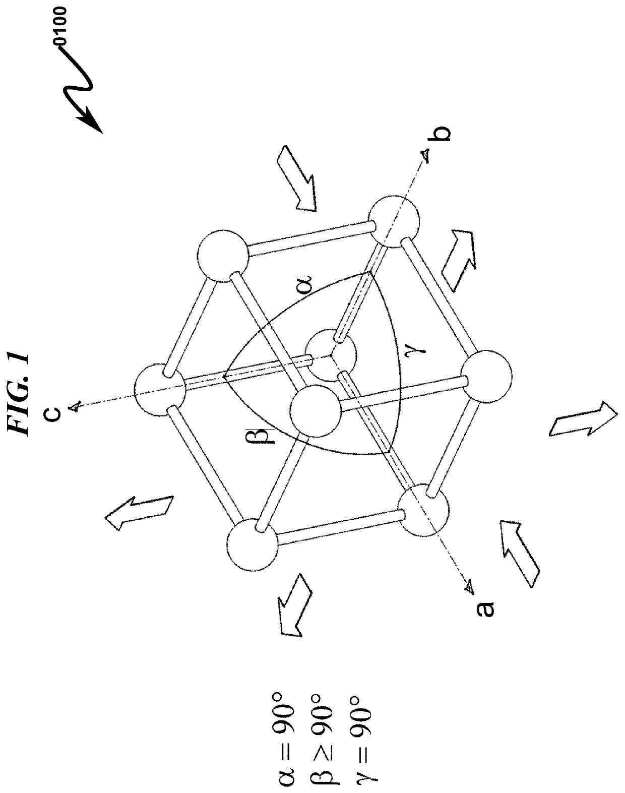
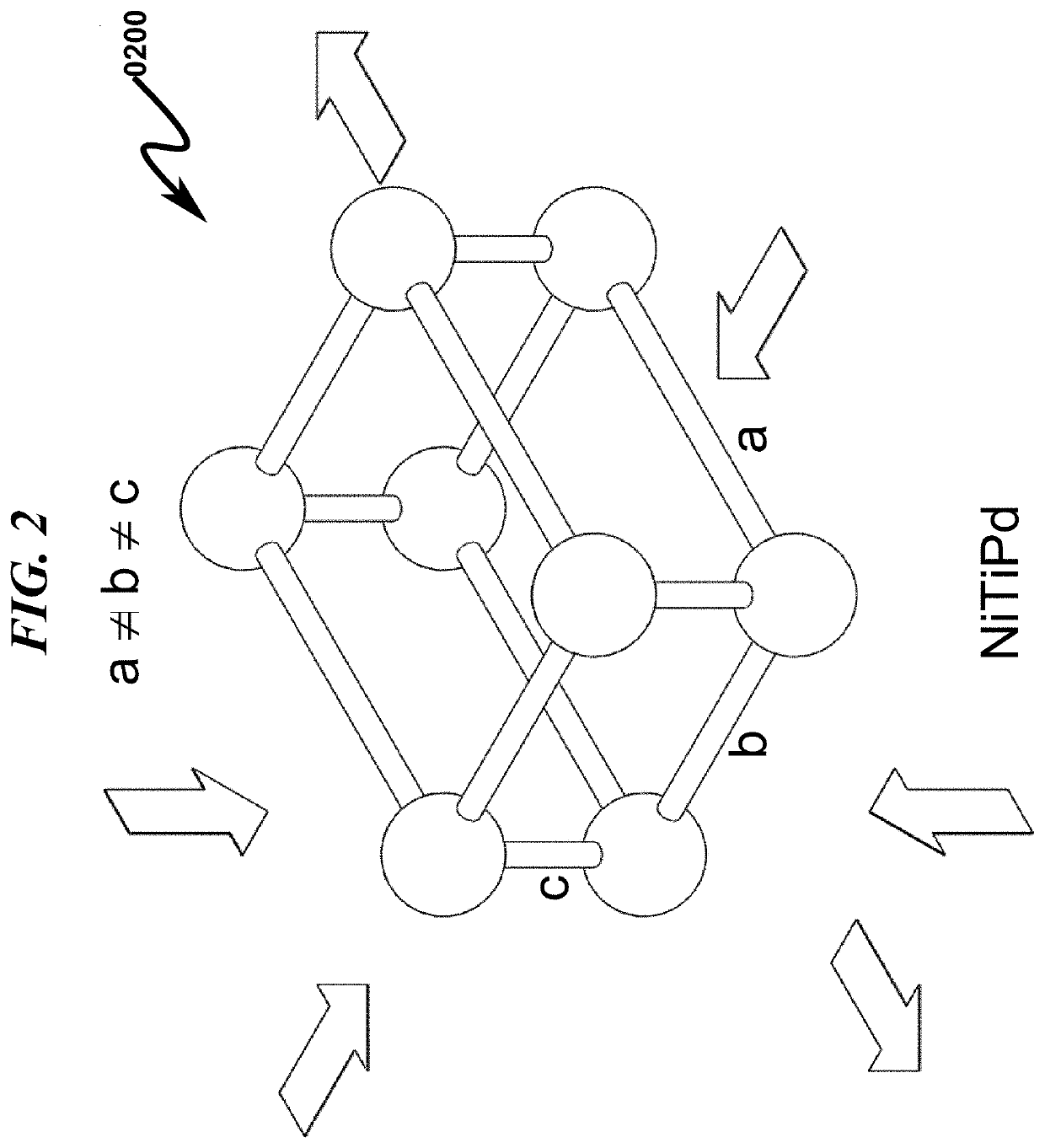
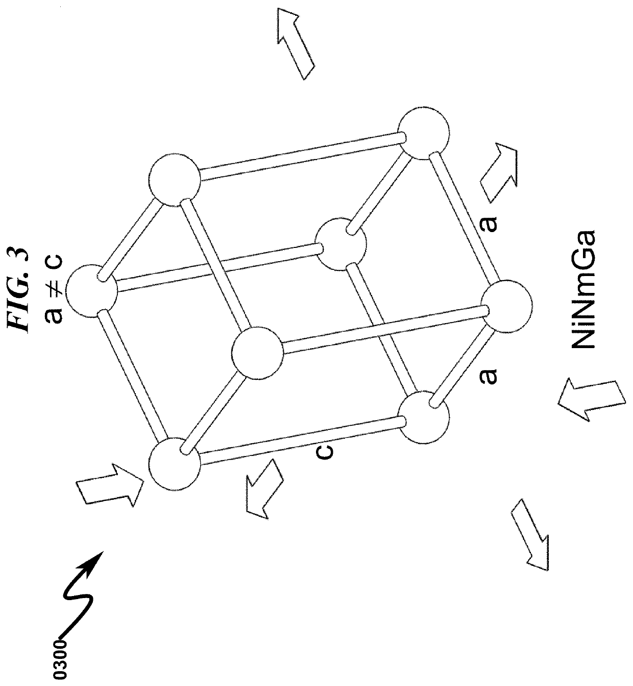
While the thermal expansion anisotropy provides the potential for NTE materials, randomly oriented variants do not provide macroscopic NTE.
This is similar to the well-established idea that a liquid phase will sample its crystalline form due to random thermal fluctuations, but this sample is quickly destroyed by other random thermal fluctuations.
Unfortunately, this effect only occurs below 32 K (see J. Arvanitidis, K. Papagelis, S. Margadonna, K. Prassides, A. N. Fitch, Temperature-induced valence transition and associated lattice collapse in samarium fulleride.
Unfortunately, the application potential of NTE ceramics is limited due to their low fracture toughness (see V. Srikanth, E. C. Subbarao, D. K. Agrawal, C.-Y.
While carbon reinforced composites are a more attractive alternative for tailored thermal expansion compensation, harnessing carbon's low CTE requires complex and expensive composite fabrication techniques.
This means on a grain scale it is possible to have neighbors with very different CTE's resulting in intergranular stresses.
However, it might be due to error from the thin sample size.
This is a response that materials exhibiting isotropic thermal expansion characteristics, such as Invar and ZrW2O8, cannot achieve.
These magnitudes are the limiting factors for the achievable macroscopic thermal expansion coefficients that can be achieved in a bulk material.
Torsion causes non-uniform deformation outward from the center of the torque.
These changes may or may not be designed to achieve a specific function.
Solid state lasers used in the telecommunications industry are currently limited in their ability to transmit a number of wavelengths along a fiber optic cable due to thermal mechanical characteristics of the laser packaging and associated solid state substrate supports.
Generally speaking, lasers used in this environment are limited in their data-rate performance by uncontrolled thermal expansion of mechanical elements associated with the laser.

Method used


Image

  • Controlled thermal coefficient product system and method
  • Controlled thermal coefficient product system and method
  • Controlled thermal coefficient product system and method

Examples


embodiment summary

[0032]Embodiments described herein comprise a combination of features and advantages intended to address various shortcomings associated with certain prior devices, systems, and methods. The foregoing has outlined rather broadly the features and technical advantages of the invention in order that the detailed description of the invention that follows may be better understood. The various characteristics described above, as well as other features, will be readily apparent to those skilled in the art upon reading the following detailed description, and by referring to the accompanying drawings. It should be appreciated by those skilled in the art that the conception and the specific embodiments disclosed may be readily utilized as a basis for modifying or designing other structures for carrying out the same purposes of the invention. It should also be realized by those skilled in the art that such equivalent constructions do not depart from the spirit and scope of the invention as set...


PUM

PropertyMeasurementUnit
temperaturesaaaaaaaaaa
thickaaaaaaaaaa
temperaturesaaaaaaaaaa

Abstract

A controlled thermal coefficient product manufacturing system and method is disclosed. The disclosed product relates to the manufacture of metallic material product (MMP) having a thermal expansion coefficient (TEC) in a predetermined range. The disclosed system and method provides for a first material deformation (FMD) of the MMP that comprises at least some of a first material phase (FMP) wherein the FMP comprises martensite randomly oriented and a first thermal expansion coefficient (FTC). In response to the FMD at least some of the FMP is oriented in at least one predetermined orientation. Subsequent to deformation, the MMP comprises a second thermal expansion coefficient (STC) that is within a predetermined range and wherein the thermal expansion of the MMP is in at least one predetermined direction. The MMP may be comprised of a second material phase (SMP) that may or may not transform to the FMP in response to the FMD.

Description

CROSS REFERENCE TO RELATED APPLICATIONSU.S Patent Applications[0001]This application is a Continuation-In-Part (CIP) patent application of and incorporates by reference U.S. Utility Patent application for SYSTEMS AND METHODS FOR TAILORING COEFFICIENTS OF THERMAL EXPANSION BETWEEN EXTREME POSITIVE AND EXTREME NEGATIVE VALUES by inventors James A. Monroe, Ibrahim Karaman, and Raymundo Arroyave, filed with the USPTO on Dec. 11, 2015, with Ser. No. 14 / 897,904, and published on May 12, 2016 as US20160130677A1.[0002]This application claims benefit under 35 U.S.C. § 120 and incorporates by reference U.S. Utility Patent application for SYSTEMS AND METHODS FOR TAILORING COEFFICIENTS OF THERMAL EXPANSION BETWEEN EXTREME POSITIVE AND EXTREME NEGATIVE VALUES by inventors James A. Monroe, Ibrahim Karaman, and Raymundo Arroyave, filed with the USPTO on Dec. 11, 2015, with Ser. No. 14 / 897,904, and published on May 12, 2016 as US20160130677A1.PCT Patent Applications[0003]U.S. Utility patent applica...

Claims


Application Information

Patent Timeline
Patent Type & Authority Patents(United States)
IPC IPC(8): C22F1/18C21D8/00F27D11/06F27D7/06C21D9/00B23K26/38C22F1/08C22F1/10B23K26/14B23K26/06B21D35/00C21D1/78B21D22/20B23K101/16B23K103/04
CPCC21D1/785C21D8/005F27D11/06F27D7/06C21D9/0068B21D35/002C22F1/10C22F1/183B23K26/38B23K26/1476B23K26/14B23K26/0648B23K26/0643C22F1/08F27D2007/066B23K2103/04B23K2101/16B21D22/20
Inventor MONROE, JAMES ALANKARAMAN, IBRAHIMARROYAVE, RAYMUNDO
Owner TEXAS A&M UNIVERSITY
Learn More