
Coated optical fibers

a technology of optical fibers and coatings, applied in the direction of synthetic resin layered products, polyurea/polyurethane coatings, textiles and paper, etc., can solve the problems of reducing the strength of the coating, increasing the transmission loss of the optical fiber, and compromising the integrity of the coating, etc., to achieve a high cavitation strength and low modulus

Inactive Publication Date: 2002-10-10
DSM IP ASSETS BV
View PDF5 Cites 59 Cited by
  • Summary
  • Abstract
  • Description
  • Claims
  • Application Information

AI Technical Summary

Benefits of technology

[0011] It is a further object of the present invention to obtain a primary coating having an equilibrium modulus of about 1.5 MPa or less and having a low actual stress level.
[0174] On the other hand, it is desired that the .alpha..sub.23 of the secondary coating is about 6.85.times.10.sup.-4 K.sup.-1 or less. Surprisingly, such a secondary coating composition shows enhanced reactivity and photosensitivity, and consequently a higher cure speed. Thus, by tuning the .alpha..sub.23 of the secondary coating a desirable balance between an acceptable stress level in the primary coating and an acceptable cure speed of the secondary can be achieved. More preferably, .alpha..sub.23 of the secondary coating is about 6.5.times.10.sup.-4 K.sup.-1 or less, particularly preferred, about 6.2.times.10.sup.-4 K.sup.-1 or less, more preferred about 6.0.times.10.sup.-4 K.sup.-1 or less, and most preferred about 5.8.times.10.sup.-4 K.sup.-1 or less.

Problems solved by technology

When optical fibers are coated with a primary coating material having an equilibrium modulus of about 2 MPa or higher, the transmission loss of the optical fibers may increase because of decreased buffering effect.
However, when using such low modulus primary coatings, and in particular, when using primary coatings having a modulus below 1.3 MPa, the strength of the coating is decreased and thus the integrity of the coating is at risk.
Hence, such coatings tend to be very fragile and can result in the formation of defects in the coating during processing or use of the coated optical fiber.
However, these coatings need further improvement in strength or integrity because defects still appear during the use of the coated optical fiber, in particular, under the influence of high stresses and temperature extremes which the coated fiber has to withstand over time (during production, cabling or when buried under the ground).
This problem is further enhanced nowadays due to the increasing line speeds for fiber drawing causing steeper cooling profiles, and allowing less time for relaxation.
During coloring, cabling and possibly in the field, the fibers may be cycled through high and low temperatures, causing comparable stress on the primary coating.
This stress has now been proven to also result in the appearance of defects within the coating.

Method used


Image

  • Coated optical fibers
  • Coated optical fibers
  • Coated optical fibers

Examples


experiment b and example 1

Comparitive Experiment B and Example 1

[0236] A commercial coating with an equilibrium modulus of 1.0 MPa was used. In comparative experiment B, the sample was cured using a dose of 1 J / cm.sup.2. The cavitation strength measured at the occurrence of the cavitation was 1.21 MPa. The storage modulus E' at 23.degree. C. of the coating E'23 is 0.97 MPa. Hence, the value of .sigma..sub.10 / E'23 was 1.25, Go=22 J / m.sup.2.

[0237] In Example 1, the sample was first cured with three short flashes of UV-light (in total about 1 cJ / cm.sup.2 or less), whereafter the sample was cured at 1 J / cm.sup.2 (as described in the Description of Test Methods above). A laboratory Macam lamp which is a 400W metal halide lamp (Macam, Flexicure system) is used to pre-cure the sample (the three short flashes of 1 cJ / cm.sup.2 or less in total): UV-light is fed into the cell by a liquid filled light guide, resulting in a cut-off of the wavelengths below 260 nm.

[0238] The cavitation strength of the coating of Example ...

example 2

[0240] A coating was formulated using 69.7 wt % of a polyether urethane acrylate oligomer having a polyether backbone comprising on average two blocks polypropylene glycol having an average Mw of about 4000 and being end-capped with ethoxy groups (the oligomer is the reaction product of a polyether polyol, toluene diisocyanate and 2-hydroxyethyl acrylate), 20.4 wt % 2-phenoxyethyl acrylate, 6.4 wt % tripropyleneglycoldiacrylate, 2.0 wt. % Lucerin TPO, 0.3 wt % DC190, 0.2 wt % DC57 and 1 wt % mercapto silane.

[0241] The equilibrium modulus was 0.6 MPa. The modulus E' at 23.degree. C. was 0.7 MPa. The relative Mooney plot is given in FIG. 4. The cavitation strength at the tenth cavity .sigma..sub.10 was measured to be 1.24 MPa after 1 J / cm.sup.2 cure (see FIG. 3); the .sigma..sub.10 / E'.sub.23 was 1.77; Go=31 J / m.sup.2.

example 3

[0242] A primary coating composition was formulated using 38.8 wt % of an aliphatic polyether-polycarbonate based urethane acrylate oligomer having an average Mw of 4000 (the oligomer is derived from 2-hydroxyethylacrylate, isophoronediisocyanate, and equal amounts of polypropyleneglycol diol and a copolymer diol of 10-15 wt % polyether / 85-90 wt % polycarbonate), 48.5 wt % of N butylurethane O ethyl acrylate (CL1039), 9.7 wt. % isodecyl acrylate and 3 wt % of Irgacure 184 photoinitiator.

[0243] The equilibrium modulus is 1.31 MPa. The calculated volumetric thermal expansion coefficient .alpha..sub.23 is 6.74.times.10.sup.-4 K.sup.-1.


PUM

PropertyMeasurementUnit
Fractionaaaaaaaaaa
Forceaaaaaaaaaa
Forceaaaaaaaaaa

Abstract

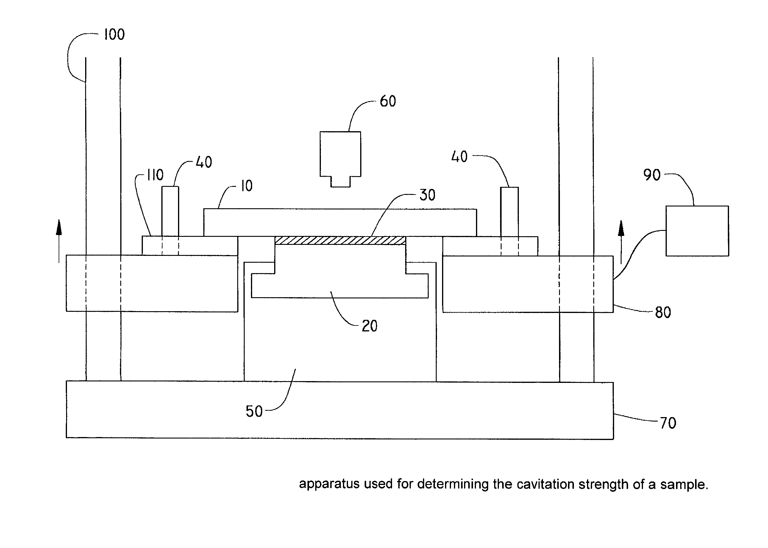
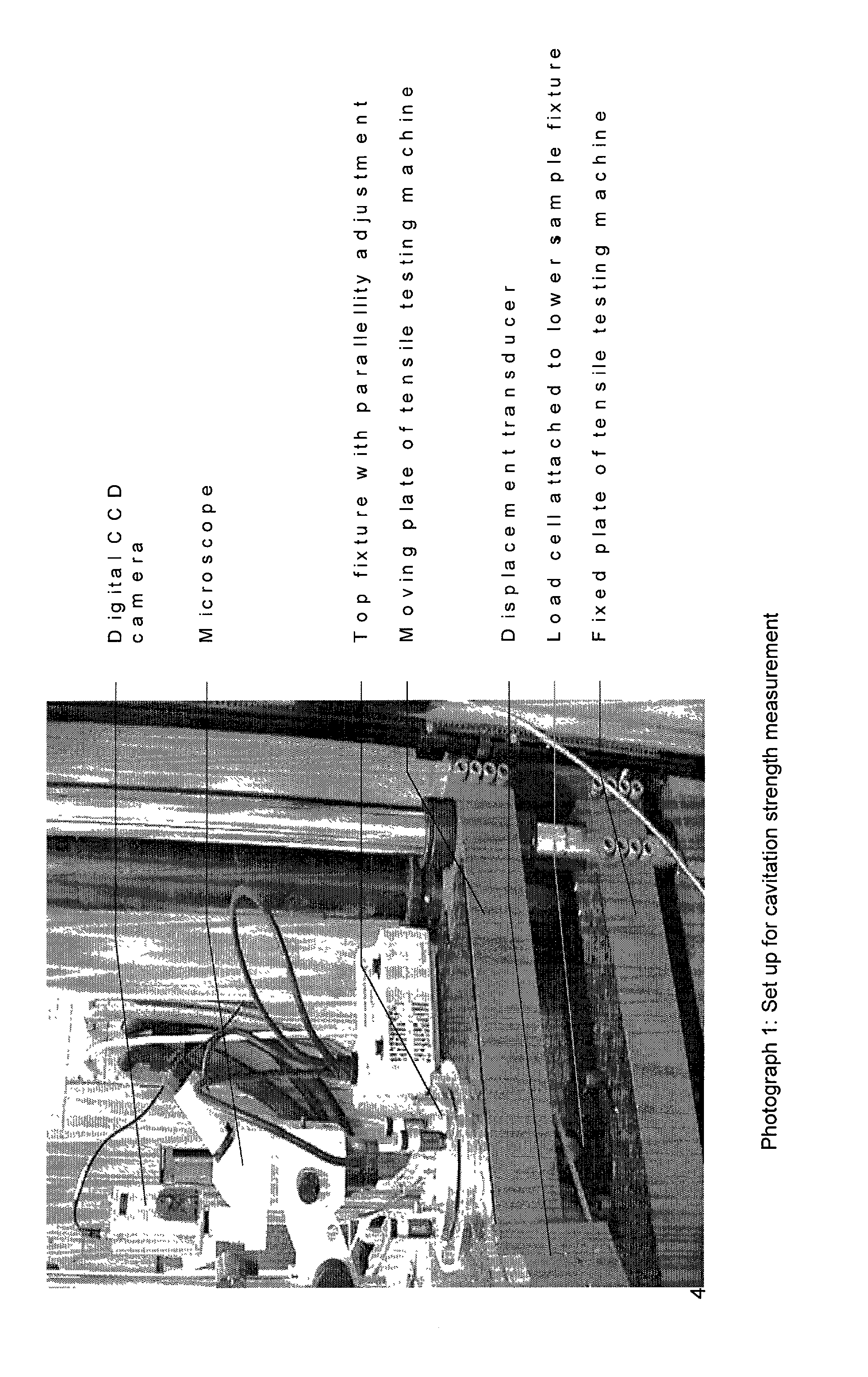
The invention relates to coated optical fibers comprising soft primary coatings and to such primary coatings for protecting glass optical fibers having a sufficient high resistance against cavitation. In particular, the primary coatings have a cavitation strength at which a tenth cavitation appears (sigma10cav) of at least about 1.0 MPa as measured at a deformation rate of 0.20% min-1 and of at least about 1.4 times their storage modulus at 23° C. The coating preferably shows strain hardening in a relative Mooney plot, preferably has a strain energy release rate Go of about 20 J / m2 or more, and preferably has a low volumetric thermal expansion coefficient. The invention furthermore provides a method and apparatus for measuring the cavitation strength of a primary coating.

Description

[0001] The present invention relates to a coated optical fiber comprising a primary and secondary coating, to a radiation curable primary coating composition, to a combination of a primary and secondary coating, and to a ribbon comprising at least one of said coated optical fibers and to a method and apparatus for measuring cavitation strength of a coating for use as a primary coating on an optical fiber.DESCRIPTION OF RELATED ART[0002] Because optical fibers are fragile and easily broken, the optical fibers are usually coated with a coating material which is a radiation curable resin composition. The transmission characteristics of optical fibers are known to be significantly affected by properties such as modulus or the like of the primary coating material which is in direct contact with the optical fibers. When optical fibers are coated with a primary coating material having an equilibrium modulus of about 2 MPa or higher, the transmission loss of the optical fibers may increase ...

Claims


Application Information

Patent Timeline
IPC IPC(8): C03C25/10C08F220/26C08F220/36C08F230/02C08G18/28C08G18/67C08G18/80C08G18/81C09D4/00C09D175/16G01L1/00
CPCC03C25/106Y10T428/2947C08F220/36C08F230/02C08G18/284C08G18/285C08G18/672C08G18/8064C08G18/8175C09D4/00C09D175/16C08F220/26Y10T428/2938Y10T428/2942Y10T428/2956G02B6/02395C08G18/48C08F220/20C08F220/302
Inventor BULTERS, MARKUS J.H.REKERS, GERRITBLEIMAN, PHILIPPE W.P.V.LINSEN, JOZEF M.H.STROEKS, ALEXANDER A.M.VAN EEKELEN, JOHANNES A.ABEL, ADRIANUS G.M.DORSCHO, MARKOSTEEMAN, PAULUS A.M.
Owner DSM IP ASSETS BV
Learn More