
Refrigerant compressor, cooling system and refrigerator

A technology for compressors and refrigerants, used in mechanical equipment, engine components, machines/engines, etc., can solve problems such as corrosion and sliding surface corrosion, reduce sliding loss, reduce friction coefficient, and achieve the effect of friction coefficient

Inactive Publication Date: 2007-03-14
PANASONIC CORP +1
View PDF2 Cites 0 Cited by
  • Summary
  • Abstract
  • Description
  • Claims
  • Application Information

AI Technical Summary

Problems solved by technology

However, if manganese phosphate treatment is performed on the mixed layer, the surface of the sliding part is corroded, and according to the following chemical reaction formula (chemical formula 1), (chemical formula 2), (chemical formula 3) of manganese phosphate treatment, two The mixed layer of molybdenum sulfide is etched away

Method used


Image

  • Refrigerant compressor, cooling system and refrigerator
  • Refrigerant compressor, cooling system and refrigerator
  • Refrigerant compressor, cooling system and refrigerator

Examples


Embodiment approach 1

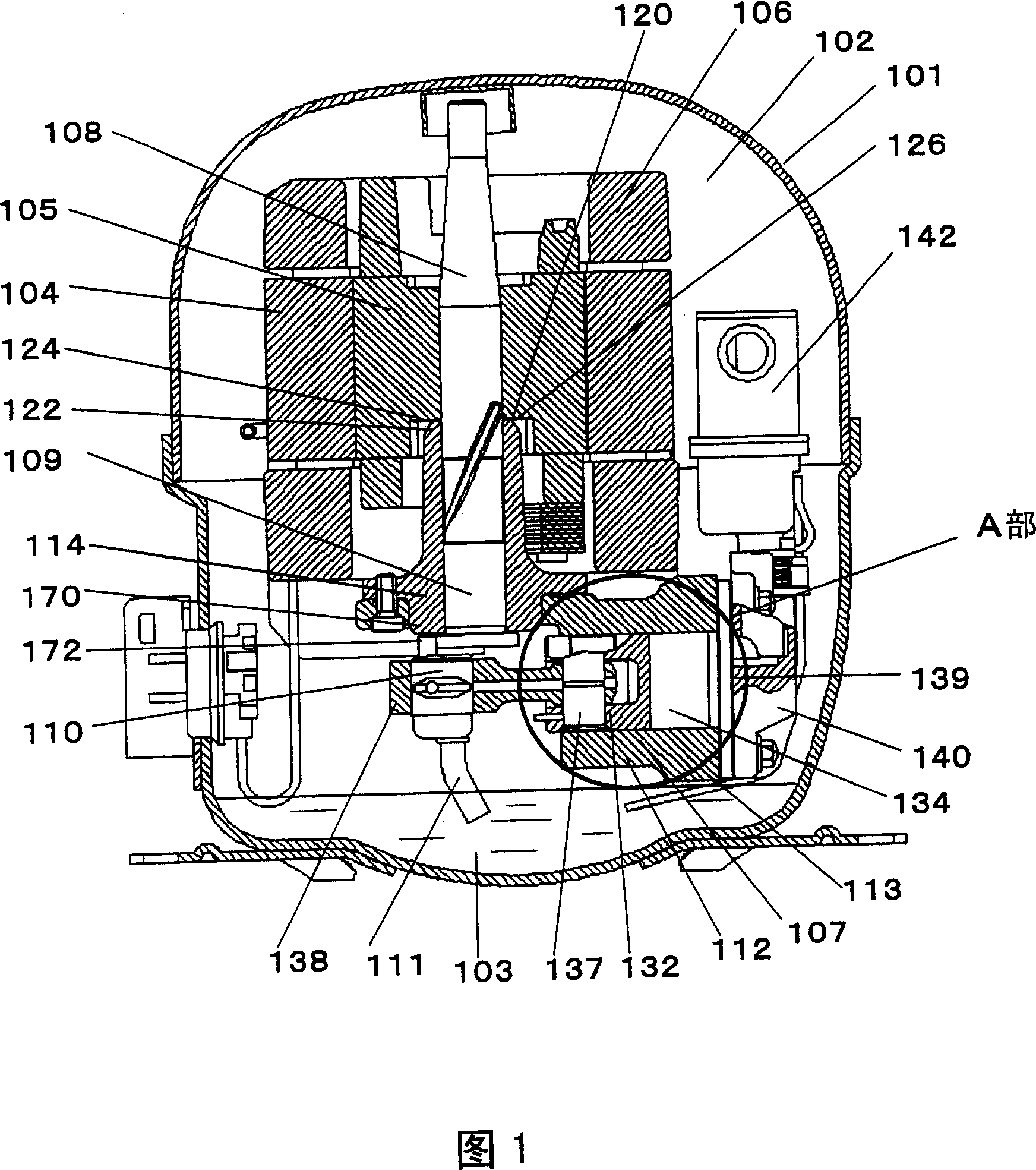
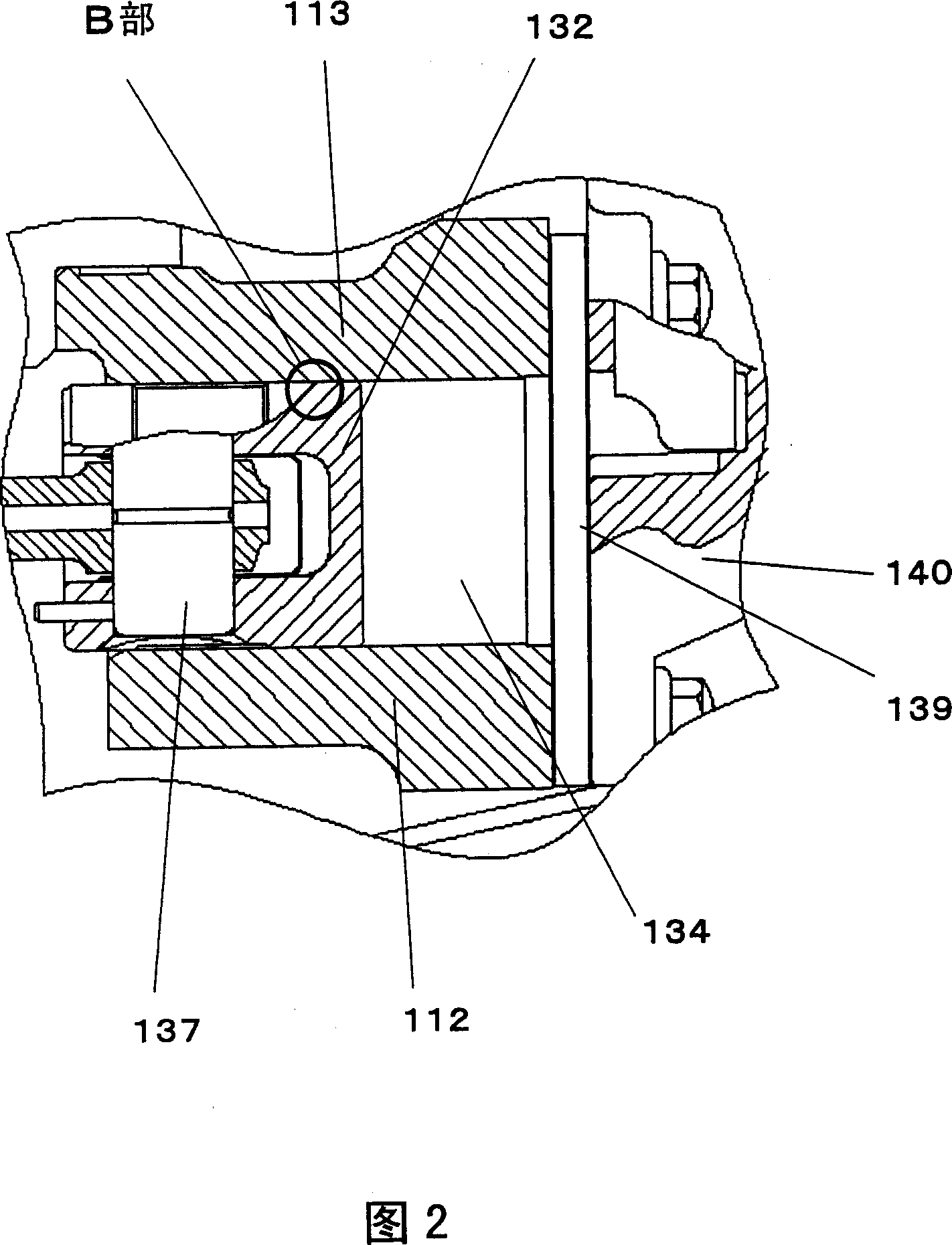
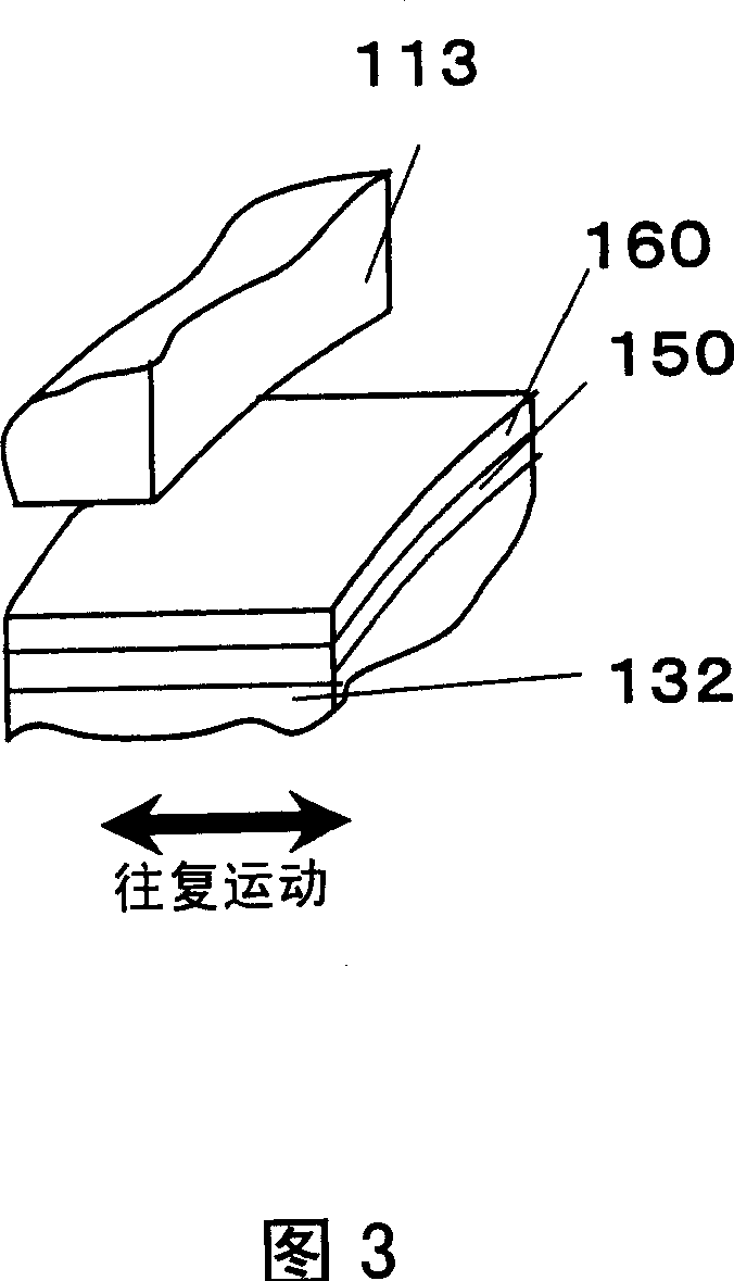
[0056] Fig. 1 is a cross-sectional view of a refrigerant compressor according to Embodiment 1 of the present invention, Fig. 2 is an enlarged view of part A in Fig. 1 , Fig. 3 is an enlarged view of part B in Fig. 2 , and Fig. 4 is a disulfide of this embodiment The formation diagram of molybdenum, Fig. 5 is a characteristic diagram showing the relationship between the gap of the piston / hole and the cooling capacity of this embodiment, Fig. 6 is a concentration distribution diagram of molybdenum disulfide of this embodiment, Fig. 7 is a graph showing this embodiment The characteristic diagram of the relationship between the concentration of molybdenum disulfide and the efficiency, Fig. 8 is the connecting rod assembly diagram of the embodiment in which the ball fixed on the connecting rod is riveted and fixed by the piston, and Fig. 9 is the household refrigerator of the embodiment Fig. 10 is a cross-sectional view of the expansion valve according to Embodiment 1.

[0057] In ...

Embodiment approach 2

[0102] 11 is a cross-sectional view of a refrigerant compressor according to Embodiment 2 of the present invention, FIG. 12 is a cross-sectional view along line C-D in FIG. 11 , and FIG. 13 is an enlarged view of part E in FIG. 12 .

[0103] In FIGS. 11 , 12 and 13 , an electric unit 204 composed of a stator 202 and a rotor 203 , and a rotary plunger compression unit 205 driven by the moving unit 204 are housed in a sealed container 201 together with oil 206 .

[0104] The compression unit 205 includes: a shaft 210 having an eccentric portion 207, a main shaft portion 208, and a sub shaft portion 209; a hydraulic cylinder 212 forming a compression chamber 211; both end surfaces of the hydraulic cylinder 212 are sealed, and the main shaft portion 208 and the sub shaft portion are respectively pivotally supported. The main bearing 213 and auxiliary bearing 214 of 209; the rotary plunger 215 that is loosely embedded in the eccentric part 207 and rolls in the compression chamber 21...


PUM

PropertyMeasurementUnit
thicknessaaaaaaaaaa
diameteraaaaaaaaaa

Abstract

A refrigerant compressor having a compression element comprising sliding components made of metallic materials, wherein a mixed layer is formed by solid-dissolving molybdenum disulfide in at least one of the sliding faces of the sliding components, and a single molybdenum disulfide layer is further formed on the surface of the mixed layer. With this configuration, initial break-in is done using the single layer, and sliding loss is reduced. Even if the single layer peels off, because the molybdenum disulfide of the mixed layer is cleaved at a low friction coefficient, solid lubrication action is attained, the friction coefficient of the sliding section is lowered, and sliding loss is reduced.

Description

technical field [0001] The present invention relates to a refrigerant compressor mainly used in household electric refrigerators and the like. Background technique [0002] In recent years, from the viewpoint of global environmental protection, high-efficiency compressors that reduce the use of fossil fuels have been actively developed. [0003] In a conventional compressor, one of the sliding parts constituting the sliding part is made of a sliding material obtained by manganese phosphate-treated iron-based material after nitriding treatment, and the other sliding part is made of anodized aluminum die-casting (For example, refer to Japanese Patent Application Laid-Open No. 6-117371). [0004] Fig. 14 is a sectional view showing a conventional refrigerant compressor described in JP-A-6-117371. As shown in FIG. 14 , the airtight container 1 stores oil 2 at the bottom, and accommodates an electric unit 5 composed of a stator 3 and a rotor 4 , and a reciprocating compression ...

Claims


Application Information

Patent Timeline
Patent Type & Authority Applications(China)
IPC IPC(8): F04B39/00
CPCF05C2253/12F04C18/3564F04B39/023F04C23/008F04B39/0005F05C2203/086F04B39/126F04B39/02
Inventor 岩田博光片山诚梅冈郁友吉见祐基川端淳太石田贵规石渡正人
Owner PANASONIC CORP
Learn More