
Light metal surface micro plasma ceramic coating technology

A micro-plasma and ceramic coating technology, applied in a light field, can solve the problems of limited wear life, low hardness, poor bonding strength, etc., and achieve the effects of good overall toughness, high bonding strength and high production efficiency

Inactive Publication Date: 2006-06-14
上海施迈尔精密陶瓷有限公司
View PDF0 Cites 14 Cited by
  • Summary
  • Abstract
  • Description
  • Claims
  • Application Information

AI Technical Summary

Problems solved by technology

[0002] The traditional ceramic spraying technology is mainly ceramic powder plasma spraying and ceramic rod thermal spraying technology. The ceramic powder is thermally melted, and then the melted liquid-phase ceramics are sent to the substrate through compressed air, and the liquid-phase ceramic body is cooled and hardened, thereby covering the substrate to form a ceramic coating. Since the ceramic layer is an external coating, Therefore, the bonding strength between the coating and the base material is not very good, and it is easy to cause the coating to peel off during use, and due to the limitation of the thermal melting process in the spraying process, the surface finish of the coating is poor, and it is often necessary to carry out high-strength spraying. Grinding is used to meet the smoothness requirements, but due to poor bonding strength, the surface ceramic coating is easy to peel off due to the effect of surface compressive stress during processing; hard anodized layers with better bonding strength, such as hard chrome layers, have higher hardness. Low, the wear life is greatly limited, and more serious heavy metal ion environmental pollution will be generated in the production process

Method used


Image

  • Light metal surface micro plasma ceramic coating technology

Examples


Embodiment

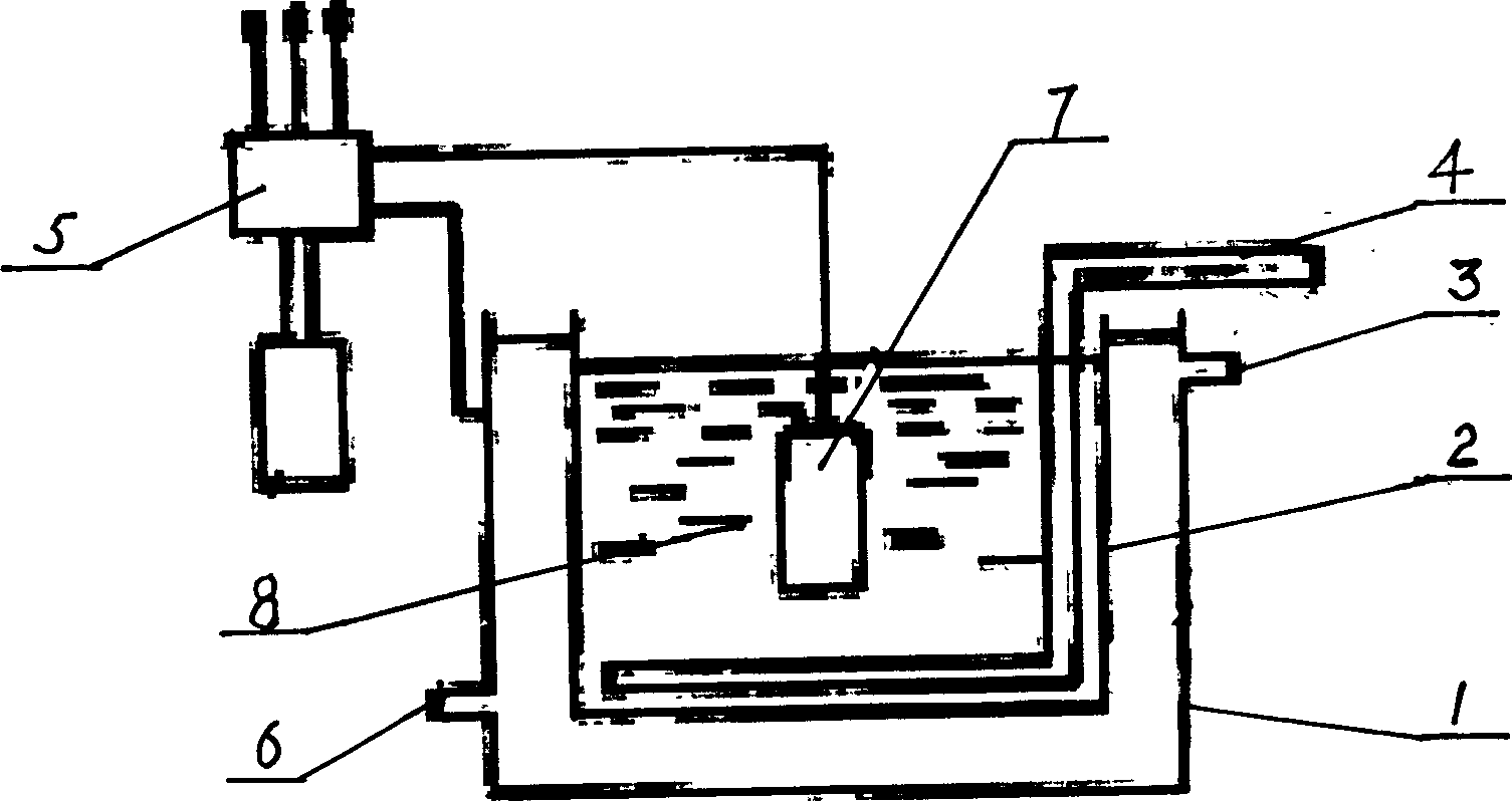
[0032] like figure 1 As shown, it is a schematic structural diagram of the micro-arc oxidation equipment used for the micro-plasma ceramic coating process on the surface of light metal. The micro-arc oxidation equipment used for the micro-plasma ceramic coating process on the surface of light metal is characterized in that the Tube 1, inner electrolytic tube 2, circulating cooling water outlet 3, pipeline 4, control power supply 5, circulating cooling water inlet 6, inner electrolytic tube 2 is installed in outer electrolytic tube 1, between outer electrolytic tube 1 and inner electrolytic tube 2 There is circulating cooling water, the circulating cooling water outlet 3 is set at the upper end of the outer electrolytic tube 1, the circulating cooling water inlet 6 is set at the lower end of the outer electrolytic tube 1, the pipeline 4 with compressed air is placed in the inner electrolytic tube 2, and the control The power supply 5 is located above the outer electrolytic cyli...


PUM

PropertyMeasurementUnit
thicknessaaaaaaaaaa
hardnessaaaaaaaaaa
friction coefficientaaaaaaaaaa

Abstract

The present invention provides a light metal surface microplasma ceramic coating process. It is characterized by that it utilizes electrolytic method to make oxidic film be grown on surface of base material. Its electrolytic solution is made up by using the following raw materials: (by wt%) 5-10% of alkaline salt solution, 4-6% of Na2O2, 0.5-1% of NaF, 2-3% of CH3COONa, 1-3% of Na3VO3 and 80-87% of H2O. Besides, said invention also provides the concrete steps of its electrolytic method.

Description

technical field [0001] The invention relates to a micro-plasma ceramic coating process on the surface of light metal, which can be used in the corrosion resistance of automobile industry, aerospace industry, shipbuilding industry, photoelectric technology industry, micro-electromechanical industry, information industry, pharmaceutical industry, orthopedic transplantation, and satellite communication industry. , Wear resistance, high temperature resistance, high voltage resistance, coating hardness, coating thickness, burr removal, dimensional precision, metal fatigue strength, coating adhesion, etc., belong to the field of ceramic technology. Background technique [0002] The traditional ceramic spraying technology is mainly ceramic powder plasma spraying and ceramic rod thermal spraying technology. The ceramic powder is thermally melted, and then the melted liquid-phase ceramics are sent to the substrate through compressed air, and the liquid-phase ceramic body is cooled an...

Claims


Application Information

Patent Timeline
Patent Type & Authority Applications(China)
IPC IPC(8): C04B37/02
Inventor 李广仁李戈张万林王俊唐源生戴端木
Owner 上海施迈尔精密陶瓷有限公司
Learn More