3-D machining method of micromechanical parts
A processing method and micro-mechanical technology, applied in computer control, instruments, simulators, etc., can solve problems such as difficult processing, limited processing materials, expensive equipment, etc.
- Summary
- Abstract
- Description
- Claims
- Application Information
AI Technical Summary
Problems solved by technology
Method used
Image
Examples
specific Embodiment approach 1
[0014] Specific Embodiment 1: This embodiment is a way to obtain a micro three-dimensional structure (or three-dimensional parts) by using SPM combined with a micro-motion three-dimensional workbench: by changing the shape and range of the SPM scan in the XY plane in the horizontal direction, and at the same time through the XY Moving the worktable in the plane can realize concave or convex three-dimensional structure processing. As shown in Figure 3, its processing sequence is as follows: the needle tip and the surface in section AB are in the processing state, and the needle tip and surface in section BC move downward in the Z direction of the worktable, so that the needle tip and the processed sample are separated from each other, so the surface is not processed. The CD section returns to the state of the AB section through the movement of the Z-direction worktable, and continues to process, thus completing the processing of the AB and CD sections and keeping the BC section ...
specific Embodiment approach 2
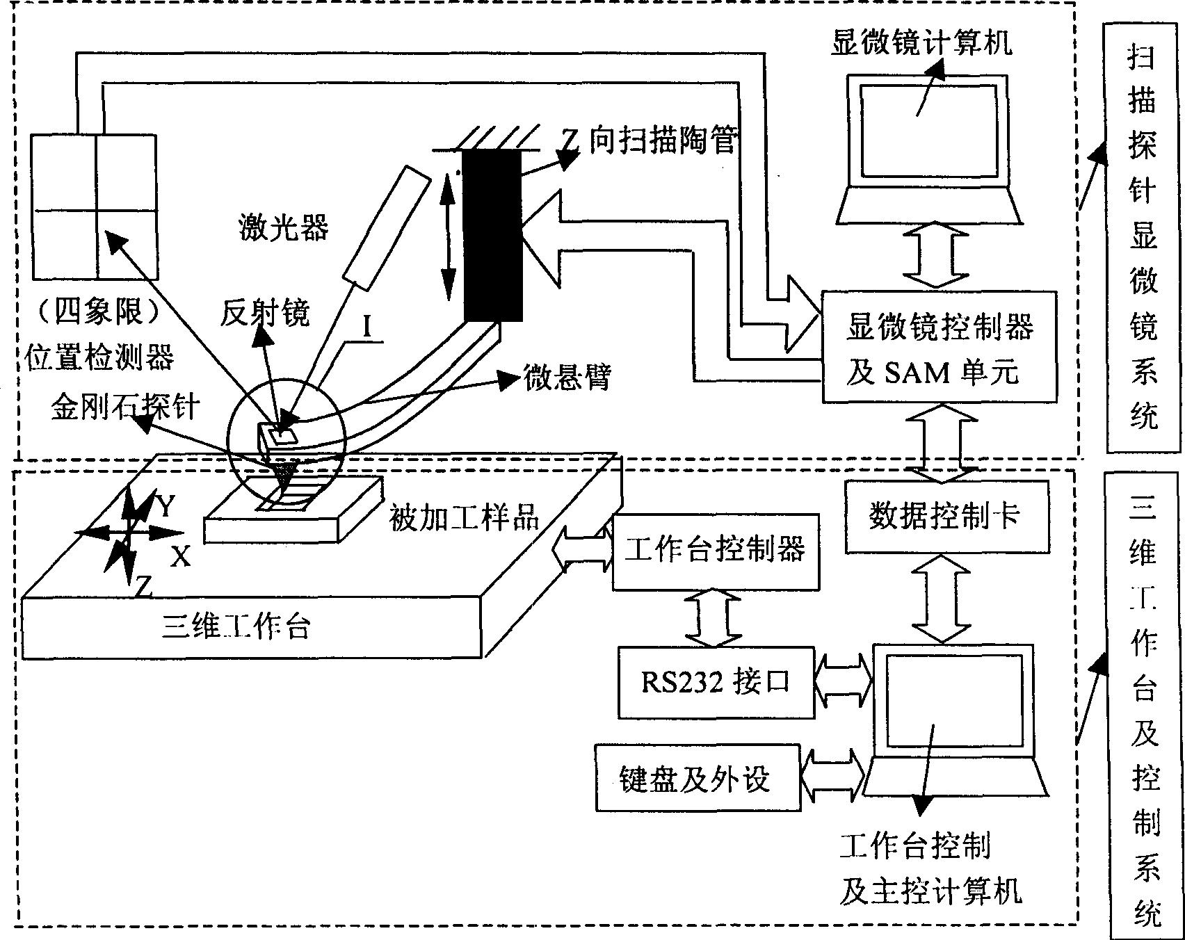
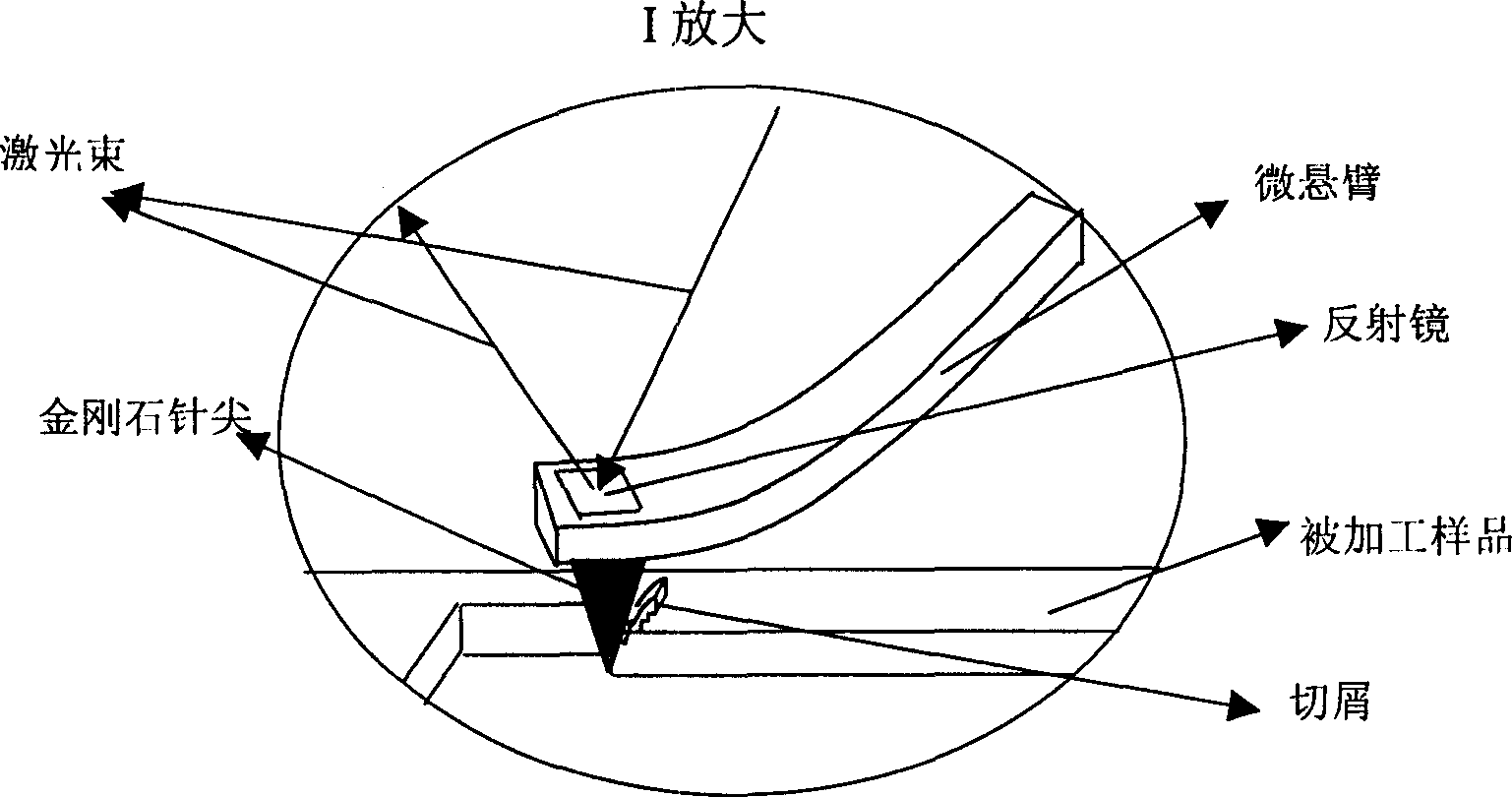
[0016] Specific implementation mode two: see figure 1 , put a single crystal copper sheet with smooth surface quality on the three-dimensional workbench. First adjust and set the SPM parameter value and the working parameters of the workbench, such as feed rate, scanning speed, Setpoint setting voltage representing the vertical pressure, and manually control the keyboard of the computer to control the controller of the SPM system to make the processing probe approach The sample, the probe reaches the sample and embeds on the surface of the sample, automatically stops after reaching the SPM setting value we selected, and drives the workbench to start scanning processing in the XY horizontal plane, and the Setpoint setting voltage representing the vertical pressure remains constant during processing. After processing a circle, figure or square groove A area (see Figure 4, that is, the AB section of Figure 3), the computer keyboard is manually controlled and the probe is lifted t...
specific Embodiment approach 3
[0017] Specific implementation mode three: this implementation mode is processing such as Figure 14 Processing steps for the graph shown: First, divide the graph to be processed into six rectangles in the horizontal direction, such as Figure 13As shown, the computer processes the graphics according to the pre-designed path: control the vertical movement of the three-dimensional worktable, so that the diamond tip is in contact with the workpiece and pressed into it. When the pressing force, that is, the preset tip load reaches the designed rectangle 1 After the machining depth is required, the computer controls the three-dimensional workbench to stop feeding in the vertical direction, and the X and Y directions of the workbench start to automatically process the rectangle 1. At this time, the computer controls the micro-motion three-dimensional worktable to move two-dimensionally through the program, and moves the rectangle 2 of the next processing area of the workpiece to ...
PUM
 Abstract
Description
Claims
Application Information
 - R&D
- Intellectual Property
- Life Sciences
- Materials
- Tech Scout
- Unparalleled Data Quality
- Higher Quality Content
- 60% Fewer Hallucinations
Browse by: Latest US Patents, China's latest patents, Technical Efficacy Thesaurus, Application Domain, Technology Topic, Popular Technical Reports.
© 2025 PatSnap. All rights reserved.Legal|Privacy policy|Modern Slavery Act Transparency Statement|Sitemap|About US| Contact US: help@patsnap.com


