Tubular direct carbon fuel cell poly-generation device and method
A fuel cell and polygeneration technology, which is applied to fuel cell components, fuel cells, carbon monoxide, etc., can solve the problems of low utilization efficiency and limited utilization market, and achieve the effect of easy control, prevention of breakage, and feedback adjustment.
- Summary
- Abstract
- Description
- Claims
- Application Information
AI Technical Summary
Problems solved by technology
Method used
Image

Examples
Embodiment 1
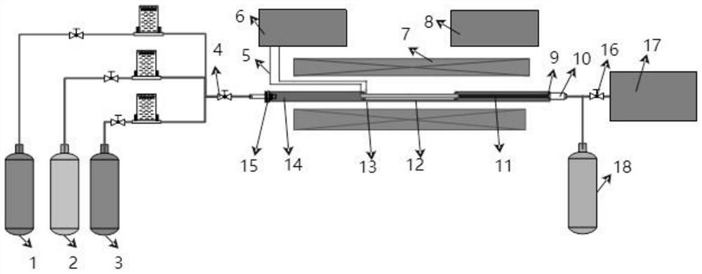
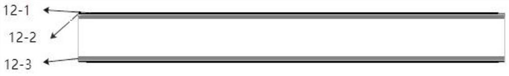
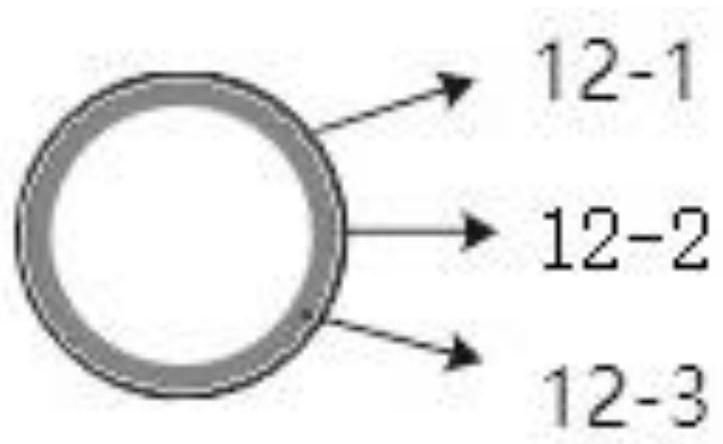
[0046] Such as figure 1 with Figure 2a ~ Figure 2b As shown, the device for tubular direct carbon fuel cell polygeneration in this embodiment includes an electric heating furnace 7 and a corundum tube 14 that penetrates in the electric heating furnace 7 and extends out of the electric heating furnace 7 at both ends. The corundum tube The middle part of 14 is provided with a notch for accommodating the tubular direct carbon fuel cell 12, and the corundum tube 14 is divided into a front half and a rear half, and the two ends of the tubular direct carbon fuel cell 12 are connected with the corundum tube 14 respectively. The outlet of the first half is connected to the inlet of the second half, and the tubular direct carbon fuel cell 12 is a hollow structure composed of a cathode layer 12-1, an electrolyte layer 12-2 and an anode layer 12-3 that are sequentially coated from outside to inside , the hollow structure is used to fill carbonaceous fuel, the surface of the cathode lay...
Embodiment 2
[0061] This embodiment includes the following steps:
[0062] Step 1. Use silver paste to brush the cathode layer 12-1 and the surface of the anode layer 12-3 of the tubular direct carbon fuel cell 12 respectively as a current collector, and weld a pair of silver wires 5 on the current collector, and then Put the powder of carbonaceous fuel into the hollow structure of the tubular direct carbon fuel cell 12, and use foamed nickel to seal both ends; the tubular direct carbon fuel cell 12 is a cathode layer 12 coated sequentially from outside to inside -1 is the hollow structure composed of the cathode, the electrolyte layer 12-2 and the anode layer 12-3, the anode, the cathode layer 12-1 is lanthanum strontium cobalt iron oxide LSCF, and the solution layer 12-2 is yttrium stabilized zirconia YSZ, the anode layer 12-3 is a porous composite of Ni and yttrium-stabilized zirconia YSZ, and the outer diameter of the tubular direct carbon fuel cell 12 is 6.00 mm, the inner diameter is...
Embodiment 3
[0072] The difference between this example and Example 2 is that the carbonaceous fuel used is Shenmu Tianyuan semi-coke.
[0073] Figure 7 It is the current-voltage curve graph of the tubular direct carbon fuel cell of the present embodiment at 750°C, 800°C, and 850°C, from Figure 7 It can be seen that the corresponding peak power densities of the tubular direct carbon fuel cell at 750°C, 800°C, and 850°C are 1.07W, 1.51W, and 1.99W, which shows that the tubular direct carbon fuel cell in this embodiment is more cogeneration. The device has high reactivity to semi-coke fuel, and the output performance of the tubular direct carbon fuel cell is good.
[0074] Figure 8 It is the performance curve diagram when the discharge current of the tubular direct carbon fuel cell of the present embodiment is 3A at 850° C., from Figure 8 It can be seen that after 40 minutes of discharge, the voltage of the tubular direct carbon fuel cell dropped from the initial 0.568V to 0.519V.
...
PUM
| Property | Measurement | Unit |
|---|---|---|
| thickness | aaaaa | aaaaa |
| thickness | aaaaa | aaaaa |
| thickness | aaaaa | aaaaa |
Abstract
Description
Claims
Application Information
 - R&D
- Intellectual Property
- Life Sciences
- Materials
- Tech Scout
- Unparalleled Data Quality
- Higher Quality Content
- 60% Fewer Hallucinations
Browse by: Latest US Patents, China's latest patents, Technical Efficacy Thesaurus, Application Domain, Technology Topic, Popular Technical Reports.
© 2025 PatSnap. All rights reserved.Legal|Privacy policy|Modern Slavery Act Transparency Statement|Sitemap|About US| Contact US: help@patsnap.com