Weight removing machine based on dynamic balance mechanism of rotor shaft of turbocharger

A technology of turbocharger and turbine rotor, which is applied in the direction of grinding machine parts, grinding frames, grinding drives, etc. Fracture and other problems to achieve the effect of reducing the difficulty of correction, reducing the vibration value and improving the stability

Pending Publication Date: 2022-02-22
LIAONING JIDIAN POLYTECHNIC
View PDF0 Cites 0 Cited by
  • Summary
  • Abstract
  • Description
  • Claims
  • Application Information

AI Technical Summary

Problems solved by technology

Therefore, for the turbine rotor working at high speed, even a small unbalance may cause large vibration and noise, accelerate the wear of bearings and sealing parts, reduce the efficiency of the supercharger, affect the working performance and precision of the equipment, shorten the The service life will affect the quality of the product. In severe cases, it will cause the turbine to collide with the casing, resulting in fracture and damage to the rotating parts of the machine. In order to ensure the reliability of the turbocharger, the turbine rotor must be dynamically balanced
[0003] The supercharger rotor is the core component of the supercharger. During high-speed rotation, the imbalance of the rotor will cause large vibration and noise, which will directly cause the wear of the floating bearing, thrust bearing and even the sealing parts, and reduce the performance of the supercharger. The service life also lays hidden dangers for safe driving. High-speed dynamic balance is a detection method and processing method that reduces the vibration value of the workpiece during high-speed rotation and reduces vibration wear by measuring the unbalance and correcting it.
Now some small and medium-sized enterprises often measure the size and orientation of the unbalance of the turbine rotor on the dynamic balance measuring machine, and then manually use an ordinary drilling machine to perform de-duplication correction. The error is very large, and repeated detection and correction are required, and the balance process cycle is long. , low efficiency, poor precision

Method used


Image

  • Weight removing machine based on dynamic balance mechanism of rotor shaft of turbocharger
  • Weight removing machine based on dynamic balance mechanism of rotor shaft of turbocharger
  • Weight removing machine based on dynamic balance mechanism of rotor shaft of turbocharger

Examples


Embodiment 1

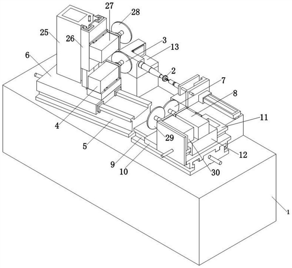
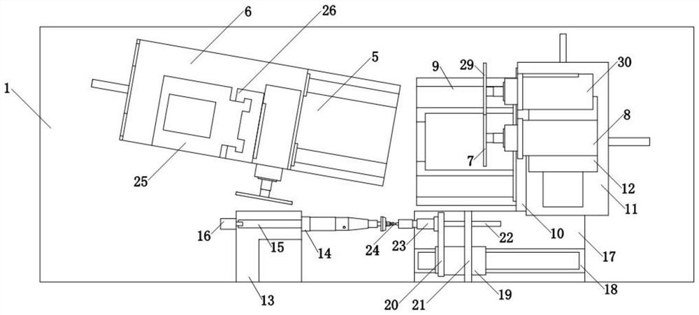
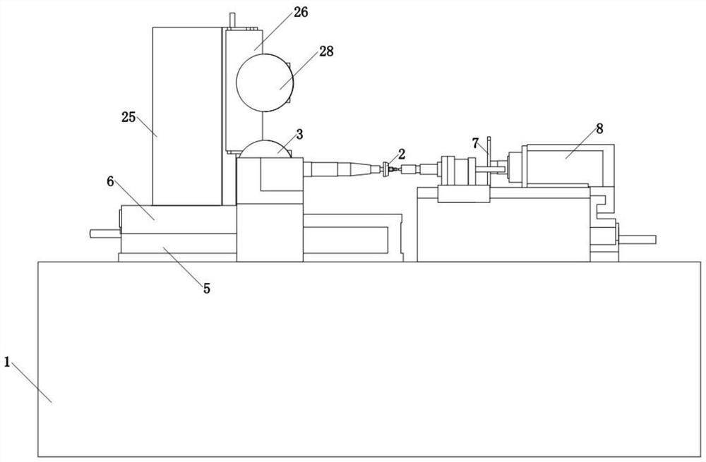
[0064] Such as Figure 1-Figure 3 As shown, a de-weighting machine based on the dynamic balancing mechanism of the turbocharger rotor shaft proposed by the embodiment of the present invention includes a base 1, the upper surface of which is fixed to hold one end of the turbine rotor shaft 2 and drive the turbine rotor The clamping mechanism for the rotation of the shaft 2, the upper surface of the base 1 is fixed with a positioning mechanism for tightening the other end of the turbine rotor shaft 2; The first moving unit on the upper surface of the base 1, the moving direction of the first moving unit is inclined at an angle relative to the axis of the turbine rotor shaft, the moving part of the first moving unit is connected with the first grinding unit, and the first moving unit The first grinding unit is driven to reciprocate between the grinding position for grinding the turbine rotor shaft impeller and the retracted position retreating from the grinding position; the turb...

Embodiment 2

[0067] This embodiment is based on Embodiment 1, the first grinding unit includes a first grinding wheel 3, the center of the first grinding wheel 3 is connected to the output shaft of the first motor 4, and the first motor 4 is used to drive the first grinding wheel 3 to rotate and grind at a high speed Turbine rotor shaft impeller.

[0068] Further, the first mobile unit includes a first workbench 5 fixed on the upper surface of the base 1, on the first workbench 5 is provided a first sliding platform 6 slidingly connected to it through a sliding mechanism, the first sliding The upper surface of table 6 is fixedly connected with the first motor 4 of the first grinding unit, the outer casing of the first motor 4 of the first grinding unit is fixed on the upper surface of the first sliding table 6, the first motor 4 is a high-speed motor, and the high-speed motor drives The first grinding wheel 3 rotates at high speed; the first ball screw mechanism is provided in the groove p...

Embodiment 3

[0071] This embodiment is based on Embodiment 1, the second grinding unit includes a second grinding wheel 7, the center of the second grinding wheel 7 is connected to the output shaft of the second motor 8, and the second motor 8 is used to drive the second grinding wheel 7 to rotate and grind at a high speed Turbine rotor shaft port.

[0072] Further, the second mobile unit includes a second workbench 9 fixed on the upper surface of the machine base 1, the second workbench 9 is slidably connected with the second slide table 10 through a sliding mechanism, and a recess is opened inside the second workbench 9. Groove, the second ball screw mechanism used to drive the second sliding table 10 to reciprocate along the second worktable 9 is provided in the groove provided by the second worktable 9, and the second ball screw mechanism is selected from the prior art The ball screw mechanism that machine tool feed adopts; The upper surface of described second slide table 10 is also f...


PUM


Abstract

The invention discloses a weight removing machine based on a dynamic balance mechanism of a rotor shaft of a turbocharger. The weight removing machine comprises a machine base, and a clamping mechanism, a positioning mechanism, a turbine rotor shaft impeller grinding mechanism and a turbine rotor shaft port grinding mechanism are fixed to the upper surface of the machine base. The turbine rotor shaft impeller grinding mechanism comprises a first moving unit fixed to the upper surface of the machine base, and the first moving unit is used for driving a first grinding unit to move back and forth to grind a turbine rotor shaft impeller. The turbine rotor shaft port grinding mechanism comprises a second moving unit fixed to the upper surface of the machine base, and the second moving unit is used for driving a second grinding unit to move back and forth to grind a turbine rotor shaft port. According to the weight removing machine based on the dynamic balance mechanism of the rotor shaft of the turbocharger, the unbalance amount on a turbine rotor shaft port and an impeller of the turbocharger is reduced in a weight removing mode, then the vibration value during high-speed rotation is reduced, and the stability of the turbine rotor shaft is improved.

Description

technical field [0001] The invention relates to the technical field of dynamic balancing equipment, in particular to a weight removing machine based on the dynamic balancing mechanism of a turbocharger rotor shaft. Background technique [0002] The turbine rotor shaft is a key part of the turbocharger, and its working speed is generally as high as tens of thousands of revolutions per minute, or even more than two hundred thousand revolutions per minute. Due to the uneven material of the turbine, the defects of the blank, the processing and assembly errors or uneven wear, etc., it is inevitable to cause uneven mass distribution, resulting in unbalanced quantities, resulting in the offset of the center of mass and the inconsistency between the inertial spindle and the rotating spindle, resulting in produce centrifugal force. Since the magnitude of the centrifugal force is proportional to the square of the angular velocity, that is to say, the higher the rotational speed of th...

Claims


Application Information

Patent Timeline
Patent Type & Authority Applications(China)
IPC IPC(8): B24B27/00B24B41/06B24B41/02B24B47/04B24B47/12B24B47/22B24B53/00
CPCB24B27/0023B24B41/06B24B41/02B24B47/04B24B47/12B24B47/22B24B53/003
Inventor 王岩周新
Owner LIAONING JIDIAN POLYTECHNIC
Why Eureka
Try Eureka