Duty ratio adjusting circuit of clock signal, chip and duty ratio adjusting method

A clock signal, adjusting circuit technology, applied in information storage, digital memory information, transforming continuous pulse trains into pulse train devices with required patterns, etc. Poor and other problems, to achieve good linearity

Pending Publication Date: 2022-02-15
XI AN UNIIC SEMICON CO LTD
View PDF0 Cites 0 Cited by
  • Summary
  • Abstract
  • Description
  • Claims
  • Application Information

AI Technical Summary

Problems solved by technology

The working principle of the digital delay line is mainly to change the slope of the rising and falling edges of the clock signal by adding a capacitive load behind the inverter, thereby affecting the transmission delay of the clock signal
With the change of operating voltage, temperature and process, the step of this digital delay line changes greatly, and the linearity is relatively poor
Especially in some larger-sized crafts, it becomes very difficult to adjust the training or duty cycle through the digital delay line

Method used


Image

  • Duty ratio adjusting circuit of clock signal, chip and duty ratio adjusting method
  • Duty ratio adjusting circuit of clock signal, chip and duty ratio adjusting method
  • Duty ratio adjusting circuit of clock signal, chip and duty ratio adjusting method

Examples


Embodiment Construction

[0030] The following will clearly and completely describe the technical solutions in the embodiments of the present application with reference to the accompanying drawings in the embodiments of the present application. Obviously, the described embodiments are only part of the embodiments of the present application, not all of them. Based on the embodiments in this application, all other embodiments obtained by persons of ordinary skill in the art without making creative efforts belong to the scope of protection of this application.

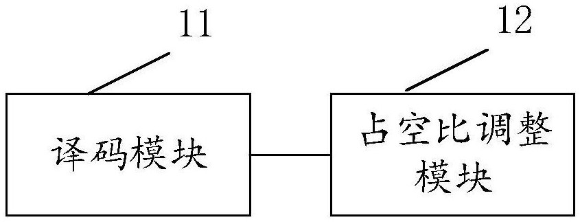
[0031] See figure 1 , is a schematic diagram of functional modules of the first embodiment of the clock signal duty ratio adjustment circuit of the present invention, specifically including: a decoding module 11 and a duty ratio adjustment module 12 .

[0032] Wherein, the decoding module 11 receives the configuration signal mrtrm, and generates the control signal SEL based on the configuration signal mrtrm. Wherein, the configuration signal mrtr...


PUM


Abstract

The invention provides a duty ratio adjusting circuit of a clock signal, a chip and a duty ratio adjusting method. The circuit comprises a decoding module and a duty ratio adjusting module, and the decoding module receives a configuration signal and generates a control signal based on the configuration signal; and the duty ratio adjusting module is connected with the decoding module and receives the clock signal, and the duty ratio adjusting module delays the rising edge or the falling edge of the received clock signal by at least one stepping value based on the control signal so as to generate an adjusted clock signal. In the duty ratio adjusting circuit, the input and the output of the duty ratio adjusting circuit are analog signals, so that the stepping of the duty ratio adjusting circuit can be smaller, and the stepping linearity of the duty ratio adjusting circuit is better; and the stepping of the duty ratio adjusting circuit changes little along with the working voltage, the temperature and the process angle, and particularly, the duty ratio adjusting circuit is a very good choice when the duty ratio of a high-speed clock path needs to be adjusted on the large-size process.

Description

technical field [0001] The invention relates to the technical field of clock signal adjustment, in particular to a clock signal duty ratio adjustment circuit, a chip and a duty ratio adjustment method. Background technique [0002] In the design of high-speed DRAM products, in order to meet the problem of chip speed, it is necessary to place a delay line on the clock path to adjust the duty cycle of the input clock. With the upgrade of the DRAM product interface, the input clock speed is getting higher and higher, and the linearity requirements for the delay line step are also getting higher and higher. At the same time, it is required that the delay line step change with PVT as small as possible. [0003] At present, digital delay lines are generally used in high-speed DRAM products to complete the adjustment of the clock duty cycle. The working principle of the digital delay line is mainly to change the slope of the rising and falling edges of the clock signal by adding a...

Claims


Application Information

Patent Timeline
IPC IPC(8): G11C11/4076H03K5/156
CPCG11C11/4076H03K5/156
Inventor 贾雪绒
Owner XI AN UNIIC SEMICON CO LTD
Why Eureka
Try Eureka