Injection molding machine having a mechanical amplifier

An amplifier, mechanical technology, used in instruments, force/torque/work measuring instruments, measuring devices, etc., to solve problems such as unfavorable measurement results, influence, etc.

Active Publication Date: 2010-11-03
ENGEL AUSTRIA
View PDF10 Cites 0 Cited by
  • Summary
  • Abstract
  • Description
  • Claims
  • Application Information

AI Technical Summary

Problems solved by technology

[0006] In the state of the art, indirect measurements are carried out via reference poles, which can adversely affect the measurement results, especially in the event of strong vibrating movements
Furthermore, this measuring instrument is located on the side of the plate facing the toggle lever, making it difficult to retrofit existing injection molding machines

Method used


Image

  • Injection molding machine having a mechanical amplifier
  • Injection molding machine having a mechanical amplifier
  • Injection molding machine having a mechanical amplifier

Examples


Embodiment Construction

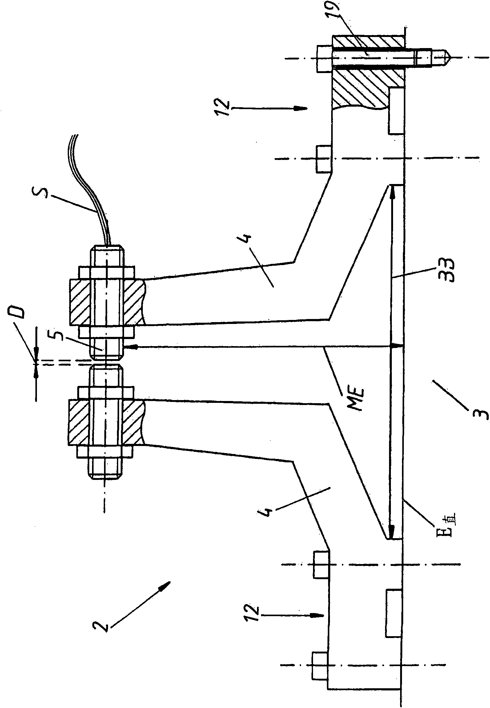
[0027] figure 1 A detail of the mechanical amplifier 2 is shown, wherein an extension 4 substantially perpendicular to the flexure surface E of the machine part 3 can be seen. The extension 4 is configured as an L-shape or a mirror-symmetrical L-shape. In this case, the fastening regions 12 (flanges) are arranged at a distance BB from one another on the machine part 3 . In this case, this distance BB is slightly greater than the distance ME between measuring sensor 5 and machine part 3 . here figure 1 , the machine part 3 is not bent or deformed, so the distance D between the two parts of the measuring sensor 5 is relatively small or minimal, and thus the distance between the extensions 4 is also relatively small or minimal.

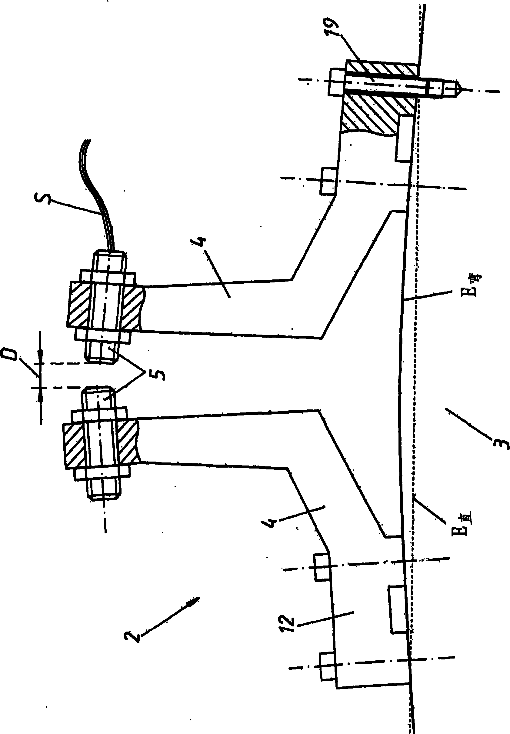
[0028] opposite of this, figure 2 A strong curvature of the machine part 3 is shown (illustrated exaggeratedly), so that the flexure surface Ebend is curved relative to the straight flexure surface E shown with dashed lines. The bending of the mach...


PUM


Abstract

The invention provides an injection molding machine having a mechanical amplifier. The machine has a mechanical amplifier (2) for determining force e.g. tool-locking force or injection force, of the machine. The amplifier is designed in the form of two extensions (4) that are arranged at a distance (D) from each other and are separated from a machine part (3), where the extensions are attached to a deformation area of the machine part. The amplifier has a measuring sensor (5) that directly measures the distance between the extensions and supplies the measured distance to a controlling and regulating unit, where the distance changes during the deformation of the machine part.

Description

technical field [0001] The invention relates to an injection molding machine with a mechanical amplifier for detecting forces of the injection molding machine, in particular mold locking forces or injection forces, wherein the forces are inferred from deformations of machine parts . Furthermore, the invention relates to a mechanical amplifier for an injection molding machine. Background technique [0002] There is often a problem with the locking force in the injection molding machine, the measurement of which can best be used to deduce the actual locking force. A possible starting point for this is the measurement of the beam elongation, for example with the aid of strain gauges. But such measurements are rather inaccurate and costly. [0003] EP 0 024 518 proposes to measure the bending deformation occurring on the end plate of the injection molding machine due to the forces guided on the one hand by the cross member and on the other hand by the toggle mechanism, which ...

Claims


Application Information

Patent Timeline
Patent Type & Authority Applications(China)
IPC IPC(8): B29C45/76G01L5/00
CPCB29C2945/7618B29C45/5008B29C2945/76224B29C2045/5032G01L5/0076B29C45/7653B29C2945/76013G01B7/14
Inventor G·维姆鲍尔
Owner ENGEL AUSTRIA
Why Eureka
Try Eureka