Non-ablative heat protection/heat insulation/bearing integrated material and preparation method thereof

A heat-proof, non-burning technology, applied in chemical instruments and methods, lighting and heating equipment, aerospace vehicle heat-proof devices, etc., can solve the problems of high cost, difficult to be reusable, long cycle, etc., to achieve temperature and resistance Good ablation performance, good interface bonding strength, good mechanical reinforcement and toughening effect

Active Publication Date: 2021-08-13
NAT UNIV OF DEFENSE TECH
View PDF17 Cites 3 Cited by
  • Summary
  • Abstract
  • Description
  • Claims
  • Application Information

AI Technical Summary

Problems solved by technology

Therefore, the preparation process of the core layer and the panel is relatively complicated and the cycle is very long, resulting in high manufacturing and use costs of the sandwich insulation structure
In addition, since the nanopore structure of the core airgel material will be destroyed by the huge surface tension of water after drying in water, the material will appear micron-scale cracks [Yang Hailong, Hu Zijun, Yang Jingxing, etc. The impact of the structure on the appearance. Journal of Composite Materials, 2019, 36(04): 964-971.], if the aircraft encounters a rainy environment when it returns, it will be difficult for the heat-resistant structure to be reusable
[0008] Therefore, the existing high-temperature-resistant and heat-insulating integrated materials have problems such as complex preparation process, long cycle, high cost, and difficulty in reusability after drying in the rain. Low thermal conductivity and high strength performance, it is difficult to meet the requirements of reusable high-speed aerospace vehicles, spacecraft, etc.

Method used


Image

  • Non-ablative heat protection/heat insulation/bearing integrated material and preparation method thereof
  • Non-ablative heat protection/heat insulation/bearing integrated material and preparation method thereof
  • Non-ablative heat protection/heat insulation/bearing integrated material and preparation method thereof

Examples


Embodiment 1

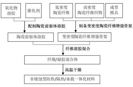
[0038] The preparation method of the non-ablative heat-proof / heat-insulation / carrying integrated material, the steps are as follows:

[0039] (1) Preparation of variable density ceramic fiber reinforced skeleton

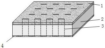
[0040] Make the bulk density 0.10g / cm 3 , a thickness of 5mm, a quartz fiber layer with a fiber diameter of 0.5~3μm as the middle layer 2, and a bulk density of 0.50g / cm 3 , a quartz fiber fabric with a thickness of 2 mm and a fiber diameter of 6-8 μm is used as the upper surface layer 1, and the bulk density is 0.50 g / cm 3 , a quartz fiber fabric with a thickness of 0.5 mm and a fiber diameter of 6 to 8 μm is used as the lower surface layer 4, the above three layers are laminated, and the quartz ceramic fiber thread 3 is used for stitching (stitch spacing 5 mm), and the three layers are formed into an integral prefabricated part; Forming molds are used (for conventional plate-shaped integral prefabricated parts, molds including upper and lower panels can be used, ...

Embodiment 2

[0050] The preparation method of the non-ablative heat-proof / heat-insulation / carrying integrated material, the steps are as follows:

[0051] (1) Preparation of variable density ceramic fiber reinforced skeleton

[0052] Make the bulk density 0.30g / cm 3 , a thickness of 60mm, a mullite fiber layer with a fiber diameter of 3~4μm as the middle layer 2, and a bulk density of 1.0g / cm 3 , a silicon carbide fiber fabric with a thickness of 4 mm and a fiber diameter of 8 to 12 μm is used as the upper surface layer 1, and the bulk density is 1.0 g / cm 3 , a quartz fiber fabric with a thickness of 0.5 mm and a fiber diameter of 6-8 μm is used as the lower surface layer 4, and the above three layers are laminated, and the silicon carbide ceramic fiber thread 3 is used for stitching (stitch spacing 30 mm), and the three layers are formed into an overall prefabricated part ; Clamping and fixing the overall prefabricated part with a forming mold to obtain a variable-density ceramic fiber ...

Embodiment 3

[0061] (1) Preparation of variable density ceramic fiber reinforced skeleton

[0062] Make the bulk density 0.23g / cm 3 , thickness 27.5mm, fiber diameter of 4 ~ 5μm aluminum silicate fiber layer as the middle layer 2, bulk density 0.75g / cm 3 , a high silica fiber fabric with a thickness of 2mm and a fiber diameter of 12-15μm is used as the upper surface layer 1, and the bulk density is 0.75g / cm 3 , a high silica fiber fabric with a thickness of 0.5 mm and a fiber diameter of 12 to 15 μm is used as the lower surface layer 4, and the above three layers are laminated, and the high silica ceramic fiber thread 3 is used for stitching (stitch spacing 20 mm), and the three layers are formed Integral prefabricated part; the integral prefabricated part is clamped and fixed by a forming mold to obtain a variable-density ceramic fiber reinforced skeleton. Among them, the middle layer is made of aluminum silicate fibers, and the upper and lower layers of the high-silica fiber fabric are...


PUM

PropertyMeasurementUnit
densityaaaaaaaaaa
thicknessaaaaaaaaaa
densityaaaaaaaaaa

Abstract

The invention relates to the technical field of heat-proof / heat-insulation / bearing materials, and provides a non-ablative heat-proof / heat-insulation / bearing integrated material and a preparation method thereof, the non-ablative heat-proof / heat-insulation / bearing integrated material comprises a variable-density ceramic fiber reinforced skeleton and nano-porous ceramic filled in the variable-density ceramic fiber reinforced skeleton; and the variable-density ceramic fiber reinforced framework sequentially comprises an upper surface layer (1), a middle layer (2) and a lower surface layer (4), and all the layers form an integral structure through needling and sewing of ceramic fiber lines (3). The mass percent of the nano porous ceramic in the non-ablative heat protection / heat insulation / bearing integrated material is 35-65%; the volume density of the upper surface layer and the lower surface layer of the variable-density ceramic fiber reinforced framework is 0.50-1.0 g / cm < 3 >, and the thickness is 0.5-4 mm; and the volume density of the middle layer of the variable-density ceramic fiber reinforced framework is 0.10-0.30 g / cm < 3 >, and the thickness of the middle layer is 5-60 mm.

Description

technical field [0001] The present invention generally relates to the technical field of heat protection / heat insulation / carrying materials, and in particular to a preparation method of a non-ablative heat protection / heat insulation / carrying integrated material. Background technique [0002] Reusable high-speed aerospace vehicles and spacecraft, etc., need to fly at high speed in the atmosphere for many times for a long time, and the large area of ​​the body (ship) faces severe aerothermal and aerodynamic loads, and its surface temperature can reach 400~1500℃, which is Ensure that the internal equipment of the fuselage is at normal operating temperature (generally ≤80°C), precisely control its flight trajectory in the atmosphere, and if the performance of the material does not decrease after returning to the ground through the rainy environment, the large-area thermal protection system of the fuselage must adopt high A high-performance reusable heat-proof / insulation / load-bea...

Claims


Application Information

Patent Timeline
Patent Type & Authority Applications(China)
IPC IPC(8): B32B18/00B32B5/06B32B7/02B32B37/00B32B38/08B32B38/16F26B23/00F27B5/00B64G1/58
CPCB32B5/02B32B5/06B32B5/26B32B7/02B32B37/00B32B38/08B32B38/164B32B2260/021B32B2260/044B32B2262/105B32B2307/304B32B2307/558B32B2605/18B64G1/58F26B23/00F27B5/00
Inventor 姜勇刚冯坚冯军宗李良军
Owner NAT UNIV OF DEFENSE TECH
Why Eureka
Try Eureka