
Brake brake shoe for brake device

A brake device and brake brake technology, which is applied in the direction of brakes, brake parts, brake types, etc. where the brake elements interact with the track, and can solve the problems of large structural size, wear, and increase of the brake system

Pending Publication Date: 2021-05-07
邹城市广信科技开发有限责任公司
View PDF4 Cites 1 Cited by
  • Summary
  • Abstract
  • Description
  • Claims
  • Application Information

AI Technical Summary

Problems solved by technology

[0002] In the prior art, a known technology is to use non-asbestos materials to process the brake pads, and another known technology is to use powder metallurgy materials to process the brake pads. These two types of brake pads , after a certain period of use, there will be wear and tear, which will affect the braking performance and service life of the brake block. At the same time, the friction coefficient of the brake block cannot be changed. If you want to increase the braking torque of the brake, you can only increase Larger forces acting on the corresponding brake pads or an increase in the number of brakes, resulting in larger structural dimensions and increased weight of the braking system
[0003] In addition, a known technology is that ordinary steel is the base body of the brake block to inlay a large number of cemented carbide cutter heads, and overlaying copper solder on the surface of the brake block base body, only a small part of the cutter head is exposed at last. This kind of structure brake block can increase the grip force between the brake block and the track, and improve the friction coefficient of the brake block, but the processing is complicated, and it is easy to generate sparks and dust when it interacts with the track

Method used


Image

  • Brake brake shoe for brake device

Examples


Embodiment Construction

[0033] The following will clearly and completely describe the technical solutions in the embodiments of the present invention with reference to the accompanying drawings in the embodiments of the present invention. Obviously, the described embodiments are only some, not all, embodiments of the present invention. Based on the embodiments of the present invention, all other embodiments obtained by persons of ordinary skill in the art without making creative efforts belong to the protection scope of the present invention.

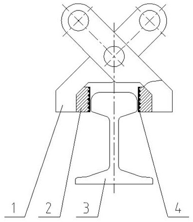
[0034] see figure 1 , the present invention provides a technical solution:

[0035] A brake block for a brake device, comprising a brake block base body 2 and a covering layer 4, the covering layer is arranged as a friction body on the braking force acting surface of the brake block base body;

[0036] At least two transverse V-shaped grooves and at least two longitudinal V-shaped grooves are processed on the braking force acting surface of the gate block bas...


PUM


Abstract

The invention discloses a brake brake shoe for a brake device. The brake brake shoe comprises a brake shoe base body and a covering layer, the covering layer serves as a friction body and is arranged on the braking force acting face of the brake shoe base body, at least two transverse V-shaped grooves and at least two longitudinal V-shaped grooves are formed in the braking force acting face of the brake block base body in a machined mode, and the transverse V-shaped grooves and the longitudinal V-shaped grooves are formed in a mutually crossed mode, so that a conical protrusion is formed on the braking force acting face of the brake block base body, and the covering layer is directly cast on the conical protrusion of the brake block base body in a casting mode, so that the brake block base body and the covering layer are cast into an integrated structure. According to the brake brake shoe for the brake device, on the basis that the abrasion performance of the bake brake block is effectively improved and the service life of the brake brake block is effectively prolonged, the reliability of the braking performance of the brake is improved, the structure is more compact, machining and manufacturing are easy and convenient, and replacement or disassembly and assembly are more convenient and faster.

Description

technical field [0001] The invention relates to the technical field of braking, in particular to a brake block for a braking device. Background technique [0002] In the prior art, a known technology is to use non-asbestos materials to process the brake pads, and another known technology is to use powder metallurgy materials to process the brake pads. These two types of brake pads , after a certain period of use, there will be wear and tear, which will affect the braking performance and service life of the brake block. At the same time, the friction coefficient of the brake block cannot be changed. If you want to increase the braking torque of the brake, you can only increase Larger forces acting on the corresponding brake pads or an increase in the number of brakes, resulting in larger structural dimensions and increased weight of the braking system. [0003] In addition, a known technology is that ordinary steel is the base body of the brake block to inlay a large number ...

Claims


Application Information

Patent Timeline
IPC IPC(8): F16D63/00F16D65/04B61H7/12
CPCB61H7/12F16D63/008F16D65/04F16D2200/0021F16D2200/0056F16D2200/0082F16D2250/0007F16D2250/0061F16D2250/0076
Inventor 唐献文朱天钰唐君源朱路群薛立军
Owner 邹城市广信科技开发有限责任公司
Learn More