
Zener diode and manufacturing method thereof

A technology of Zener diodes and manufacturing methods, applied in semiconductor/solid-state device manufacturing, semiconductor devices, electrical components, etc., can solve the problems of PN junction reverse leakage increase, electric field increase, electric field increase, etc., to achieve output noise The effect of small voltage, reducing reverse leakage and enhancing stability

Active Publication Date: 2020-11-27
JOULWATT TECH INC LTD
View PDF5 Cites 3 Cited by
  • Summary
  • Abstract
  • Description
  • Claims
  • Application Information

AI Technical Summary

Problems solved by technology

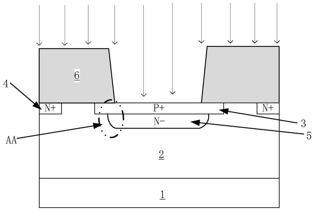
However, during the baking process of the photoresist 6 after exposure and development, the photoresist shrinkage phenomenon will occur, thereby appearing a trapezoidal structure in which the size of the bottom of the topography of the photoresist is larger than that of the top, so that the edge of the second doped region 5 The depth of the ion implantation will be correspondingly shallower, so that the distance between the peak of the impurity concentration and the P+ junction surface will be closer, and the edge of the first doped region 3 and the well region 2 and the second doped region 5 will form a camber junction reason that makes figure 1 The electric field becomes larger at the middle AA region
The increased electric field will lead to serious band-to-band tunneling effect, which will increase the reverse leakage of the PN junction of the Zener diode. When the reverse voltage continues to increase, the electric field will continue to increase, which will easily cause premature breakdown.

Method used


Image

  • Zener diode and manufacturing method thereof
  • Zener diode and manufacturing method thereof
  • Zener diode and manufacturing method thereof

Examples


Embodiment Construction

[0034] Various embodiments of the invention will be described in more detail below with reference to the accompanying drawings. In the various drawings, the same elements are denoted by the same or similar reference numerals. For the sake of clarity, various parts in the drawings have not been drawn to scale. Also, some well-known parts may not be shown. For the sake of simplicity, the semiconductor structure obtained after several steps can be described in one figure.

[0035] When describing the structure of a device, when a layer or a region is referred to as being "on" or "over" another layer or another region, it may refer to being directly above another layer or another region, or between it and Other layers or regions are also included between another layer and another region. And, if the device is turned over, the layer, one region, will be "below" or "beneath" the other layer, another region.

[0036] If it is to describe the situation directly on another layer or a...


PUM


Abstract

The invention discloses a Zener diode and a manufacturing method thereof. The Zener diode comprises: a substrate; a well region of a first doping type, which is formed in the substrate; a first dopedregion of a second doped type, which is formed in the well region, wherein the first doped type is opposite to the second doped type; and a second doped region formed below the first doped region, wherein the first part of the lower surface of the first doped region is adjacent to the well region to form a first PN junction, the second part of the lower surface of the first doped region is adjacent to the second doped region to form a second PN junction, and the second doped region adopts a hard mask to limit a boundary extending transversely in order to make the boundary of the second doped region form a plane and an included angle between the plane and the vertical direction smaller than or equal to a first angle. Uniform doping of the second doped region can be realized, so that stability of breakdown voltage of the Zener diode can be enhanced, and reverse electric leakage before breakdown can be reduced.

Description

technical field [0001] The invention relates to the technical field of semiconductor technology, in particular to a Zener diode and a manufacturing method thereof. Background technique [0002] Silicon without impurities is called intrinsic silicon. Artificially doping specific impurities in intrinsic silicon can form N-type silicon or P-type silicon that exhibits conductive properties. N-type silicon is formed by doping group V elements (such as phosphorus, arsenic, and antimony) into intrinsic silicon, and P-type silicon is formed by doping group III elements (such as boron) into intrinsic silicon. [0003] Pressing P-type silicon and N-type silicon together by alloy method or planar diffusion method will form a very thin special region near the interface between the two, called PN junction. A diode is formed by drawing a metal lead from the PN junction in the P region and the N region, respectively called the anode and the cathode. [0004] The positive and negative po...

Claims


Application Information

Patent Timeline
IPC IPC(8): H01L29/866H01L21/329H01L29/06
CPCH01L29/866H01L29/66106H01L29/0603H01L29/0684
Inventor 韩广涛
Owner JOULWATT TECH INC LTD
Learn More