
An Improved High Pressure Water Jet Rock Cutting Device

A technology of high-pressure water jet and cutting device, which is applied in the fields of mining engineering and mine geotechnical engineering, can solve the problem of high yield, achieve the effects of less thermal damage, improved cutting efficiency, and saving manpower and material resources

Active Publication Date: 2022-04-15
KUNMING UNIV OF SCI & TECH
View PDF0 Cites 0 Cited by
  • Summary
  • Abstract
  • Description
  • Claims
  • Application Information

AI Technical Summary

Problems solved by technology

In glass, stone, ceramics and other cutting and processing industries, the traditional method is to use diamond tools for cutting, sawing, milling, etc. The cutting thickness range is very large and the speed is fast. Arbitrary curve cutting processing, high yield, lower production costs, and greatly increase the added value of processed products

Method used


Image

  • An Improved High Pressure Water Jet Rock Cutting Device
  • An Improved High Pressure Water Jet Rock Cutting Device
  • An Improved High Pressure Water Jet Rock Cutting Device

Examples


Embodiment 1

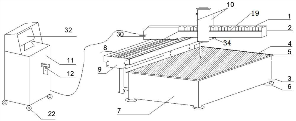
[0029] The object of the present invention is to provide an improved high-pressure water jet rock cutting device, including a high-pressure water jet cutting device, an infrared automatic probe detection device, a laser focusing CCD and a TV monitoring and control system with the same optical path, and an automatic sand removal device;

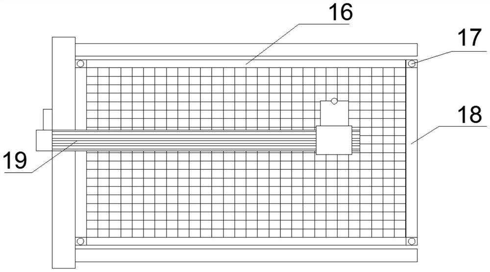
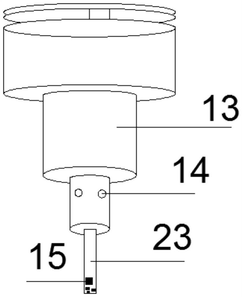
[0030] The high-pressure water jet cutting device includes an aluminum cantilever 2, a dust-proof folded cloth 1, a telescopic probe rod 13, a numerical control processing platform 4, a coordinate axis grid 5, a water tank base 7, a fixed foot 6, a water outlet 3, Water collection pipe 30, guide rail I8, bracket 9, drive motor I10, guide rail II19; the bottom of the water tank base 7 is provided with four fixed feet 6, and the water tank base 7 is provided with a CNC machining platform 4 and a CNC machining platform 4 There are X-axis coordinate ruler 16, Y-axis coordinate ruler 18 and coordinate axis grid 5. The coordinate axis grid 5 is a tra...

Embodiment 2

[0037] The structure of this embodiment is the same as that of Embodiment 1, the difference is that the water collecting pipe 30 is fixed on the cantilever 2, and the water collecting pipe 30 is fixed more securely.

[0038] The upper sides of the guide rail I8 and guide rail II19 described in this embodiment are all placed with a dust-proof folding cloth 1, and the dust-proof folding cloth protects the guide rails in a completely wrapped manner to prevent water vapor, oil pollution in the environment, and flying dust from cutting rock samples. Corrosion of the guide rail by sand. Rollers 22 are installed on the four corners of the control cabinet operating table 11; a magnet is arranged behind the wireless controller 12, which is attracted to any position of the operating table by magnetic force, and the wireless controller 12 is provided with an adjustment knob 20 and a digital positioning key 21, which can Positioning starts cutting at any position on the coordinate axis, w...


PUM


Abstract

The invention discloses an improved high-pressure water jet rock cutting device, which belongs to the fields of mining engineering and mine geotechnical engineering. The device of the present invention includes a high-pressure water jet cutting device, an infrared automatic probe detection device, a laser focusing CCD same optical path TV monitoring and control system, and an automatic sand removal device. It is mainly used for regular or irregular rock cutting technology, and specifically relates to a high-pressure water jet cutting technology, which can efficiently cut and precisely process various materials. The invention can effectively improve the cutting efficiency, the coordinate positioning cutting method can reduce the cutting error, save labor force, save energy and protect the environment, greatly improve the cutting efficiency, and have strong reliability; it conforms to the concept of green operation, and the automatic integrated operation can make the cutting operation more accurate and time-saving .

Description

technical field [0001] The invention relates to regular or irregular rock cutting technology, in particular to a high-pressure water jet cutting technology, which can efficiently cut and precisely process various materials, and is suitable for the fields of mining engineering and mine geotechnical engineering. Background technique [0002] Water cutting is also called water jet cutting or water jet cutting. High pressure water jet cutting is a special processing method. It uses a supercharger to pressurize the water to a pressure of 10MPa~400MPa or even higher. The water obtains pressure energy, and then sprays out from a fine nozzle, converting the pressure energy into kinetic energy, thus forming a high-speed jet. Cutting is to use the kinetic energy of this high-speed jet to impact and destroy the workpiece to achieve the purpose of cutting and forming. [0003] High-pressure water is sprayed out through very fine nozzles made of high-grade hard alloy, sapphire, diamond...

Claims


Application Information

Patent Timeline
Patent Type & Authority Patents(China)
IPC IPC(8): B24C1/04B24C3/00B24C5/04B24C7/00B24C9/00
CPCB24C1/045B24C3/00B24C5/04B24C7/0007B24C9/00
Inventor 李克钢刘洋李明亮秦庆词
Owner KUNMING UNIV OF SCI & TECH
Learn More