
Condenser microphone with hole in diaphragm and manufacturing method thereof

A capacitive microphone and the technology of its manufacturing method, which are applied in the field of microphones, can solve the problems of not easily thermally deformed, unstable device structure, and electrode shedding, and achieve the effects of not easily thermally deformed, economical preparation, and stable structure

Active Publication Date: 2022-01-25
FATRI UNITED TESTING & CONTROL QUANZHOU TECH CO LTD
View PDF15 Cites 0 Cited by
  • Summary
  • Abstract
  • Description
  • Claims
  • Application Information

AI Technical Summary

Problems solved by technology

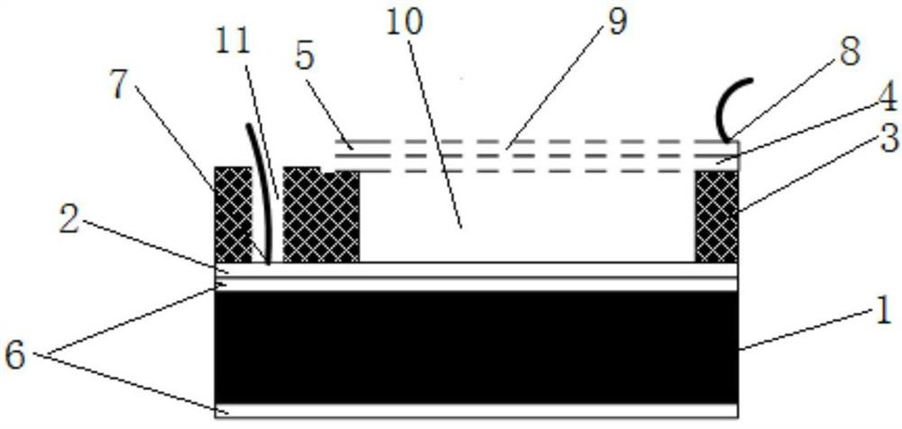
[0004] In view of the above problems, an object of the present invention is to provide a capacitive microphone with a hole in the diaphragm, through the selection of new electrode materials, it solves the problem of unstable device structure and electrode shedding caused by corrosion of the electrode metal when removing the sacrificial layer material. Problem; By preparing acoustic holes on the diaphragm, the shortcomings of the above-mentioned backhole microphones are overcome; silicon nitride is used as the diaphragm insulating layer material, silicon dioxide is used as the sacrificial layer material and the supporting material of the back plate or the use of silicon dioxide Silicon is used as the supporting material of the diaphragm insulating layer and the back plate, and silicon nitride is used as the sacrificial layer material. Compared with the commonly used materials such as polyimide, polymethyl methacrylate, and polysilicon, the device structure is more Stable, longer life, not easy to heat deformation

Method used


Image

  • Condenser microphone with hole in diaphragm and manufacturing method thereof
  • Condenser microphone with hole in diaphragm and manufacturing method thereof

Examples


Embodiment 1

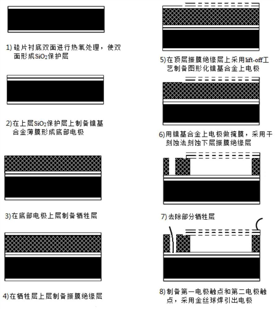
[0040] Such as figure 1As shown, a kind of capacitive microphone with holes in the diaphragm provided by the present invention includes a substrate 1, a composite diaphragm, a sacrificial layer 3, a protective layer 6 and a back plate 2; the substrate 1 is a silicon wafer; the composite diaphragm Including the diaphragm insulating layer 4 and the upper electrode 5, the upper electrode 5 is located on the upper layer of the diaphragm insulating layer 4, the composite diaphragm has good tensile stress and flexibility; the sacrificial layer 3 is located between the back plate 2 and the composite diaphragm , the back pole plate 2 and the composite diaphragm are isolated, there is an oscillation cavity 10 between the back pole plate 2 and the composite diaphragm, the composite diaphragm is provided with several acoustic holes 9, and the acoustic holes 9 on the diaphragm communicate with the oscillation cavity cavity 10; the back plate 2 and the composite diaphragm form a plate capa...

Embodiment 2

[0050] In this embodiment, the structure of the capacitive microphone with a hole in the diaphragm is basically the same as in Embodiment 1, the main difference being the material and thickness of the sacrificial layer 3, the material and thickness of the diaphragm insulating layer 4, and the back plate. 2 and the material and thickness of the upper electrode 5 and the thickness of the protective layer 6.

[0051] In this embodiment, the material of the sacrificial layer 3 is silicon nitride, and the thickness of the sacrificial layer 3 is 5 μm; the material of the diaphragm insulating layer 4 is silicon dioxide, and the thickness of the diaphragm insulating layer 4 is 0.2 μm; the nickel-based alloy is nickel-chromium-molybdenum The thickness of the nickel-chromium-molybdenum alloy back plate 2 is 0.5 μm; the thickness of the nickel-chromium-molybdenum alloy upper electrode 5 is 0.5 μm; the thickness of the protective layer 6 is 1.5 μm.

[0052] Since metal nickel itself has a...

Embodiment 3

[0055] In this embodiment, the structure of the capacitive microphone with a hole in the diaphragm is basically the same as in Embodiment 1, the main difference being the material and thickness of the sacrificial layer 3, the material and thickness of the diaphragm insulating layer 4, and the back plate. 2 and the material and thickness of the upper electrode 5 and the thickness of the protective layer 6.

[0056] In this embodiment, the material of the sacrificial layer 3 is silicon dioxide, and the thickness of the sacrificial layer 3 is 10 μm; the material of the diaphragm insulating layer 4 is silicon nitride, and the thickness of the diaphragm insulating layer 4 is 3 μm; the nickel-based alloy is nickel-copper alloy; The thickness of the nickel-copper alloy back plate 2 is 1 μm; the thickness of the nickel-copper alloy upper electrode 5 is 1 μm; the thickness of the protective layer 6 is 2 μm.


PUM

PropertyMeasurementUnit
thicknessaaaaaaaaaa
thicknessaaaaaaaaaa
thicknessaaaaaaaaaa

Abstract

The invention discloses a capacitive microphone with holes in the diaphragm, which comprises a substrate, a composite diaphragm and a back plate, the substrate is a silicon chip, the back plate is located above the substrate, and the composite diaphragm Located above the back plate, an oscillation cavity is provided between the composite diaphragm and the back plate, the composite diaphragm includes a diaphragm insulating layer and an upper electrode, and the upper electrode is located on the upper layer of the diaphragm insulating layer, so The composite diaphragm is provided with several acoustic holes, and the material of the upper electrode and / or the back plate is a nickel-based alloy; the invention also discloses a method for manufacturing a capacitive microphone with holes in the diaphragm; Acoustic holes are prepared on the diaphragm, which simplifies the processing steps, reduces the processing cost, and greatly improves the design yield through the improvement of the electrode metal.

Description

technical field [0001] The invention relates to the technical field of microphones, in particular to a capacitive microphone with holes in the diaphragm and a manufacturing method thereof. Background technique [0002] Condenser microphones include electret microphones and capacitor compression microphones. Electret microphones use the medium to provide an electrostatic field without an external bias voltage. However, the medium will leak charge. In order to maintain the stability of the charge, it is often The medium needs to be charged, and the manufacturing requirements of the medium are relatively high. At present, the electret microphone is gradually being replaced by the condenser compression microphone. The manufacturing process of the capacitive compression microphone is relatively simple. In the early stage of the capacitive microphone, the diaphragm and the back plate were respectively prepared on two silicon wafers, and then assembled by etching the cavity, bondin...

Claims


Application Information

Patent Timeline
Patent Type & Authority Patents(China)
IPC IPC(8): H04R19/04H04R7/12
CPCH04R19/04H04R7/12
Inventor 聂泳忠毛德丰
Owner FATRI UNITED TESTING & CONTROL QUANZHOU TECH CO LTD
Learn More