A kind of additive manufacturing equipment and method based on multi-field compounding

An additive manufacturing and equipment technology, applied in the field of additive manufacturing equipment based on multi-field compounding, can solve the problems of easy generation of temperature gradient, easy introduction of impurities, long production cycle, etc. Differences in field uniformity, the effect of improving surface quality

Active Publication Date: 2020-09-18
HUAZHONG UNIV OF SCI & TECH
View PDF1 Cites 0 Cited by
  • Summary
  • Abstract
  • Description
  • Claims
  • Application Information

AI Technical Summary

Problems solved by technology

Among them, the process cycle of the direct forming method is short, and the finished product can be obtained without subsequent processing of the powder, so the production efficiency is much higher than that of the indirect method, and in terms of product quality, the direct method can obtain higher purity, Density and mechanical properties, so the direct method has greater potential for the manufacture of parts, but relatively, because the direct method directly sinters or melts the material, it is easy to generate a temperature gradient during the forming process, and it is difficult to control thermal cracks well. The size and surface roughness of the parts are also limited. These disadvantages are the characteristics of the materials that limit the direct method. Compared with the direct method, the biggest difference between the indirect method and the direct method is that it needs to use organic compound powder as a binder, and requires complicated post-processing. The process and production cycle are long and the production efficiency is low, but relatively speaking, the indirect method has a lower temperature in the forming process and a smaller temperature gradient, which can reduce the occurrence of cracks, and the size of the prepared product is much larger than that of the direct method.
[0003] At present, relevant workers in this field have done some research. For example, in the paper "Additive manufacturing of ZrO2-Al2O3 ceramic components by selective laser melting" by Wikes et al. in Germany, the SLM method was used to prepare zirconia-alumina low-temperature eutectic ceramic parts. During the forming process, in order to reduce the influence of thermal stress, the powder bed was preheated to 1800°C before laser forming, and a ceramic part with a density close to 100% and a strength of 538 MPa was obtained, but the molten pool during laser melting was caused by high temperature preheating. As the size expands, the surface quality and dimensional accuracy of the parts are poor; another example is patent CN106830901A which discloses a ceramic particle for laser sintered ceramic 3D printing and a preparation method, which uses a spray granulation method to mix ceramic powder, binder, The defoaming agent is mixed and granulated, processed into ceramic particles, and then sintered with a laser. The adhesive is melted under the action of the laser to bond the particles together. This method still requires a subsequent degreasing process, and the overall forming efficiency is low.
All in all, the current additive manufacturing still has the following problems: 1. When using the direct method for additive manufacturing, defects such as cracks and pores are difficult to control due to the existence of thermal gradients, and it is difficult to control the surface quality and dimensional accuracy; 2. The indirect method of forming materials Additional pre-processing and post-processing steps are required, the forming efficiency is low, and impurities are easily introduced

Method used


Image

  • A kind of additive manufacturing equipment and method based on multi-field compounding
  • A kind of additive manufacturing equipment and method based on multi-field compounding

Examples


Embodiment Construction

[0027] In order to make the object, technical solution and advantages of the present invention clearer, the present invention will be further described in detail below in conjunction with the accompanying drawings and embodiments. It should be understood that the specific embodiments described here are only used to explain the present invention, not to limit the present invention. In addition, the technical features involved in the various embodiments of the present invention described below can be combined with each other as long as they do not constitute a conflict with each other.

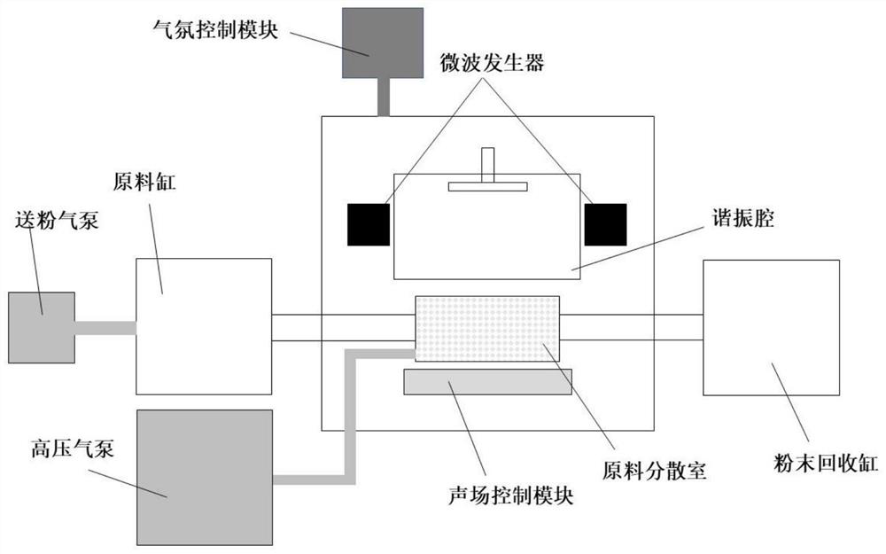
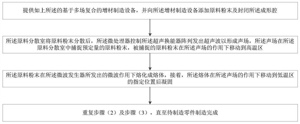
[0028] see figure 1 and figure 2, the present invention provides an additive manufacturing equipment based on multi-field compounding. The additive manufacturing equipment includes a powder conveying adjustment module, an acoustic field control module, a microwave field / thermal field control module, an atmosphere control module, a real-time monitoring module and a micro The processor, the pow...


PUM

PropertyMeasurementUnit
strengthaaaaaaaaaa

Abstract

The invention belongs to the related technical field of additive manufacturing, and discloses an additive manufacturing equipment and method based on multi-field compounding. The equipment includes a powder conveying adjustment module, a sound field control module, a microwave field / thermal field control module and a microprocessor. The powder conveying adjustment module, the sound field control module and the microwave field / heat field control module are respectively connected to the microprocessor; the powder conveying adjustment module includes a raw material dispersion chamber, and the raw material dispersion chamber is arranged in the forming cavity formed by the casing; the sound field control module is also It is arranged in the forming cavity, and it is located below the raw material dispersion chamber; the microwave field / thermal field control module includes multiple microwave generators set in the forming cavity, and the multiple microwave generators are respectively located on both sides of the forming area, and the microwave The generator and the sound field control module are respectively located on opposite sides of the raw material dispersion chamber; wherein, the forming area is divided into a high temperature area and a low temperature area, and the temperature of the high temperature area is higher than that of the low temperature area. The invention reduces the tendency of cracking, and the forming efficiency and precision can be adjusted.

Description

technical field [0001] The invention belongs to the technical field related to additive manufacturing, and more specifically relates to an additive manufacturing equipment and method based on multi-field compounding. Background technique [0002] Additive manufacturing technology is a new type of material forming method. Compared with traditional material removal-machining technology, additive manufacturing technology is a gradual accumulation and "bottom-up" manufacturing method. Compared with traditional forming technology, additive manufacturing technology has the following advantages: (1) It can manufacture parts with arbitrary complex shapes; (2) It does not rely on molds, with fast manufacturing speed and short manufacturing cycle. Since the 1990s, laser sintering has been selected (SLS), selected laser melting (SLM), stereolithography (SLA), laser cladding deposition (LENS), fused deposition modeling (FDM), etc. have been used in the forming of ceramic and hard alloy ...

Claims


Application Information

Patent Timeline
Patent Type & Authority Patents(China)
IPC IPC(8): B28B1/54B28B17/00
CPCB28B1/54B28B17/00B28B17/026Y02P10/25B33Y10/00B33Y30/00B33Y40/00B22F2999/00B22F10/20B22F2003/1054C22C29/06B22F10/32B28B1/001
Inventor 史玉升陈功刘荣臻杨宇吴甲民文世峰刘洁
Owner HUAZHONG UNIV OF SCI & TECH
Why Eureka
Try Eureka